Partially Filled Pipe (TL)
Libraries:
Simscape /
Fluids /
Isothermal Liquid /
Pipes & Fittings
Description
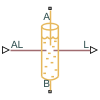
The Partially Filled Pipe (TL) block represents a pipe with the capacity for varying internal liquid levels. The pipe may also become completely dry during simulation.
In addition to liquid connections at ports A and B, port AL receives the inlet liquid level from connected blocks as a physical signal. If the value at AL is greater than zero, A is submerged. If the value at AL is less than or equal to zero, the port is exposed. The pipe liquid level is transmitted as a physical signal to connecting blocks at port L.
Port A is always higher than port B. If port A becomes exposed, the pipe can be filled through port B. When fluid enters the pipe through port B, the mass flow rate through port A is 0 until the pipe is fully filled, at which point
When to Use the Partially Filled Pipe (TL) Block
This block can be used in conjunction with the Tank (TL) block when fluid levels are expected to fall below the tank inlet. Multiple Partially Filled Pipe (TL) blocks can also be connected in series or parallel. However, because the block can only be filled at port B, if port A of one block in a parallel configuration becomes exposed, it may not be possible to refill this pipe if its connection at port B cannot refill the pipe.
Pressure Loss Over the Pipe
The pressure differential over the pipe, pA – pB, comprises losses due to wall friction and hydrostatic pressure differences between the liquid surface height and the liquid height at port A:
Friction losses depend on the fluid regime in the pipe. If the flow is laminar, the friction losses are:
where:
ν is the fluid kinematic viscosity.
fS is the Laminar friction constant for Darcy friction factor.
is the sum of the pipe length and its Aggregate equivalent length of local resistances, in proportion to the pipe fill level:
l, lmax are the liquid level and the Elevation drop from port A to port B, respectively.
Dh is the pipe hydraulic diameter. If the pipe cross-section is not circular, the hydraulic diameter is the equivalent circular diameter.
If the flow is turbulent, the friction losses are:
f is the Darcy friction factor for turbulent flows, which is determined by the empirical Haaland correlation:
where ε is the Internal surface absolute roughness parameter. The Reynolds number is based on the mass flow rate at port B and the pipe hydraulic diameter.
The hydrostatic pressure difference is
Mass Flow Rate
The flow in the pipe is dictated by the internal fluid level and the conditions at port B. The pipe can be filled or drained at B if the pipe is partially empty. If the pipe is fully filled, , and mass is conserved:
The block determines the mass of fluid in the pipe by the relative fill level of the pipe:
Energy Balance
The block balances energy flow such that when port A is submerged,
When port A is exposed,
where cv is the specific heat at constant volume, T is the fluid temperature, and h is the specific enthalpy.
Assumptions and Limitations
This block does not account for dynamic compressibility or fluid inertia, and does not model the dynamics of air (or second liquid) in the pipe.
Examples
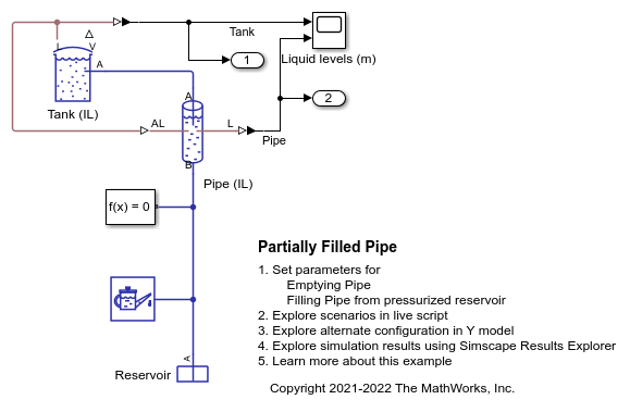
Partially Filled Pipe
The Partially Filled Pipe (IL) block used to model the emptying and filling of a tank in multiple configurations. You can use the live script provided with this example to understand the effect of different configurations.
Ports
Conserving
Input
Output
Parameters
Extended Capabilities
Version History
Introduced in R2022a