Ejector (G)

Libraries:
Simscape /
Fluids /
Gas /
Turbomachinery
Description
The Ejector (G) block models an ejector in a gas network. The ejector forces the high-pressure primary flow through a nozzle with a specific throat area, which creates a low-pressure jet that draws in the secondary flow. The expansion of the primary jet creates a throat for the secondary flow. The block assumes that the two flows mix under uniform pressure and the combined flow exits through a diffuser to recover pressure. The primary and secondary flows must be the same gas.
You can use an ejector as a pump or compressor to drive a secondary fluid. Unlike a pump or compressor, there is no external source of mechanical energy, and rather the high pressure primary fluid is the energy source that drives the secondary fluid.
Ejector Geometry
The high-pressure primary flow enters the ejector at location p and flows through a convergent-divergent nozzle with throat area Spt, which is the value of the Primary nozzle throat area parameter. The ejector chokes the primary flow at the throat (location pt) and accelerates the flow to a low-pressure supersonic jet at the primary nozzle exit (location pn). The low pressure of the supersonic primary flow jet draws in the secondary flow at location s around the nozzle.
The supersonic primary flow jet continues to expand and decrease in pressure beyond the nozzle exit until it reaches its largest area at the expanded primary flow jet (location pe). The expansion of the supersonic primary flow jet creates a fictitious aerodynamic throat for the secondary flow at location st, which is at the same location as pe. The secondary flow also chokes at the aerodynamic throat. After passing the aerodynamic throat, the primary and secondary flow mix under uniform pressure (location m). If the mixed flow is still supersonic, the flow causes a shock in the mixing chamber at location s and the diffuser (location d) decelerates the mixed flow to raise the outlet pressure.
This schematic describes the ejector where:
Location p is the primary inlet.
Location s is the secondary inlet.
Location pt is the primary nozzle throat.
Location pn is the primary nozzle exit.
Location pe is the expanded primary flow jet.
Location st is the secondary aerodynamic throat.
Location m is the mixed flow.
Location ms is the shock in the mixing chamber.
Location d is the diffuser outlet.
Mass Flow Rate
The ejector accelerates the primary gas flow through the nozzle. The mass flow rate of the primary flow is
where:
Spt is the value of the Primary nozzle throat area parameter.
is the ratio of heat capacities where cp is the specific heat at constant pressure and cv is the specific heat at constant volume.
ηp is the value of the Efficiency for primary flow through nozzle parameter.
pp is the pressure at the primary flow inlet.
pm is the pressure after the primary and secondary flow mix.
ρp is the density at the primary flow inlet.
The primary flow draws the secondary gas flow into the suction chamber and accelerates it towards the fictitious aerodynamic throat created by the expanding primary jet. The mass flow rate of the secondary flow is
where:
Sst is the area of the fictitious aerodynamic throat. The block calculates the value based on the expansion of the primary flow jet.
ηs is the value of the Efficiency for secondary suction flow parameter.
ps is the pressure at the secondary flow inlet.
ρs is the density at the secondary flow inlet.
When where the primary flow becomes choked and the mass flow rate reaches the maximum value
When the secondary flow becomes choked and the mass flow rate reaches the maximum value
Primary and Secondary Flow Relations
The flow area expansion of the supersonic primary flow jet comes from the relation
where ψpe is the value of the Efficiency for primary flow expansion parameter.
The block uses the area of the expanded supersonic primary flow jet, Spe, to calculate the flow area of the fictitious secondary flow aerodynamic throat, Sst
where:
is the value of the Area ratio of mixing chamber to throat parameter.
is the value of the Area ratio of nozzle exit to throat parameter.
The primary flow velocity of the expanded jet is
The secondary flow velocity at the aerodynamic throat is
The secondary flow velocity is limited to the choked value. When , the secondary flow reaches the maximum value of
Mixing Model
After the fictitious aerodynamic throat, the primary and secondary flows mix under uniform pressure. The mixed flow temperature is
where:
Tp is the primary flow inlet temperature. The block assumes that this value is equal to the primary flow stagnation temperature because kinetic energy at the inlet is negligible relative to the inside of the ejector.
Tm is the mixed flow temperature.
Ts is the secondary flow inlet temperature. The block assumes that this value is equal to the secondary flow stagnation temperature because kinetic energy at the inlet is negligible relative to the inside of the ejector.
R is the specific gas constant.
vm is the flow velocity after the primary and secondary flow mix.
m is the mass flow rate after the primary and secondary flow mix, meaning
The momentum balance in the mixing region is
where Sm is the cross-sectional area after the primary and secondary flow mix.
The pressure terms drop out due to the uniform pressure mixing assumption, and the mixed flow velocity is
where ψm is the value of the Efficiency for mixing parameter.
The mixed flow Mach number is
Mixed Diffuser Flow Relations
If the flow is supersonic after mixing, meaning MM > 1, a shock wave occurs. The pressure rise after the shock is
where Mm is the Mach number after the primary and secondary flow mix.
The Mach number after the shock is
After the shock, the diffuser decelerates the flow to raise the pressure. The block assumes that the kinetic energy at the diffuser outlet is negligible and decelerates the flow to stagnation pressure at pd:
If MM ≤ 1, there is no shock and
The relationship between the mixing pressure, pm, and the diffuser outlet pressure, pd, is
Critical Mode Operation
In normal operation, the primary flow is high pressure and is choked during operation. The block can also operate if the secondary flow is choked. If both the primary and secondary flows are choked, the block operates in critical mode.
The critical mixing pressure, pm*, is a low pressure threshold that causes choking in both primary and secondary flow:
The block uses the same equations as above, with pm replaced by pm*, to calculate the critical diffuser outlet pressure, pd*. If the actual outlet pressure is greater than the critical diffuser outlet pressure, then the ejector is subcritical and the block relates the mixing pressure to diffuser outlet pressure. If the actual outlet pressure is less than the critical diffuser outlet pressure, then the ejector is critical and the block limits the mixing pressure to the critical mixing pressure. This means that:
Assumptions and Limitations
The block uses isentropic ideal gas relations to derive the model equations.
The block accounts for losses due to friction, mixing, and expansion waves and shocks at the nozzle exit using empirical loss coefficients.
After the primary flow exits the nozzle, the flows do not mix until the primary flow has fully expanded.
After expansion, the flows mix under uniform pressure.
Kinetic energy at the primary flow inlet, secondary flow inlet, and diffuser outlet are negligible compared to the kinetic energy of the flow inside the ejector.
The flow is steady and one-dimensional.
The flow is adiabatic.
Model results with reversed flow may not be accurate.
Examples
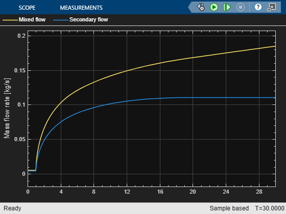
This example shows the mass flow rate of the primary and secondary flows through the Ejector (G) block.
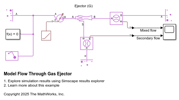
In the ejector, the primary flow that enters at port A creates a low-pressure jet that pulls in the secondary flow through port S. The mixed flow exits at port B. In this model, the secondary flow becomes choked and reaches its maximum mass flow rate.
Ports
Conserving
Parameters
References
[1] Huang, B. J., et al. "A 1-D analysis of ejector performance." International journal of refrigeration 22.5 (1999): 354-364.
[2] Chen, WeiXiong, et al. "A 1D model to predict ejector performance at critical and sub-critical operational regimes." International journal of refrigeration 36.6 (2013): 1750-1761.
Extended Capabilities
Version History
Introduced in R2023a