Optimize Latency and Area for Multirate Designs
This example shows how simulation rates in multirate designs impact the latency of and area required for HDL code and provides few recommendations for optimized code generation.
Examine the Model
The hdlcoder_multirate_delay model contains three subsystems. Open the hdlcoder_multirate_high_differential subsystem. This subsystem contains two logic operations pathways that run at different rates. The rate differential between the two rates is 10E-05, which is possibly unrealistic for practical FPGA design. This model has a Gain block that operates on floating-point data in the logic operations pathway that is faster.

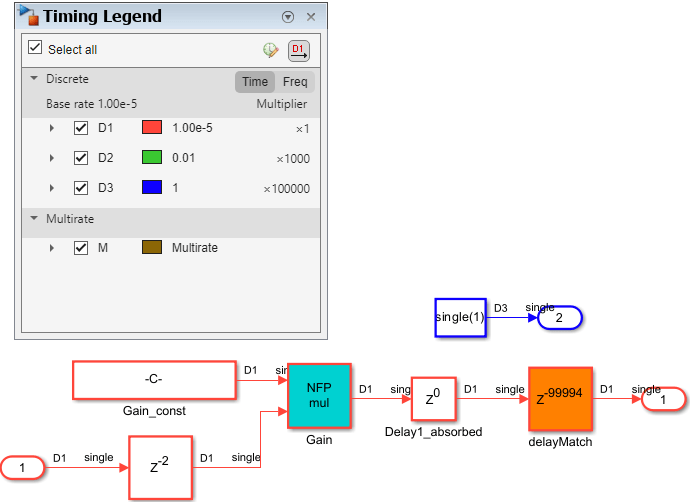
When you generate HDL code for this model, the code generation report shows that the 10,000 cycles of latency from the fast-clock rate region of the design balance across the multiple output paths of the system.

The high number of registers in the fast-clock rate region results in a large number of pipeline registers, which substantially increases the required area. To resolve this problem, you can use three different approaches:
Remove multi-rate blocks
Minimize the rate differential
Remove delay balancing on ports
Remove Multi-Rate Blocks
If your model does not require signals with different rates, you can improve the latency of the generated code by setting all blocks to the same rate. In the hdlcoder_multirate_high_differential subsystem, the sample rate for the Constant block is set to a value that causes a rate differential of 10E05 compared to the rate of the other region of the subsystem.
Change the sample rate of the Constant block to run at the same rate as the other region.

When you generate HDL code for this model, the latency in the generated model decreases significantly. The code generation report shows that only six cycles of latency from each output port are delay balanced.

Minimize the Rate Differential
If your design requires multi-rate blocks, you can minimize the rate differential to minimize the impact of delay balancing on the required number of registers. Open the hdlcoder_multirate_medium_differential subsystem. This subsystem minimizes the rate differential between the two pathways.

When you generate HDL code for the hdlcoder_multirate_medium_differential subsystem, the code generation report shows that, to balance delays, the generated code requires nearly 1,000 registers in the fast-clock rate output path.
However, the use of so many registers is not unusual for control logics that run 1,000 times faster than the system. It is important to be aware of the hardware resource constraints for these model.
To optimize the total number of required registers, enable the model configuration parameter Map pipeline delays to RAM. In the Configuration Parameters dialog box, click HDL Code Generation > Optimization. In the General tab, click Map pipeline delays to RAM. Alternatively, you can use the hdlset_param function:
>> hdlset_param(gcs, 'MapPipelineDelaysToRAM', 'on');
Remove Delay Balancing on Ports
If you want to minimize the area needed while maintaining equivalency between the design model and the generated model, turn off delay balancing for the Outport blocks with the fastest data rate.
In the hdlcoder_multirate_high_differential subsystem, the Inport block In 1 has the highest data rate. To disable delay balancing for this block, right-click the Inport block and select HDL Code > HDL Block Properties. Then, set BalanceDelays to off.
When you generate HDL code for this model, the generated code preserves the multi-rate design, but minimizes the number of required registers.