Model Single-Core, Rate-Monotonic Multitasking Application
This example shows a model designed and configured for generating embedded system code intended to execute as an application in a single-core, multitasking target environment. The application algorithm is captured as a multirate top model that is configured for C data interface code generation. The model simulates and the generated code executes based on the model configuration and a rate monotonic scheduling algorithm.
Periodic Multirate Model Set Up for Multitasking Execution
Open the example model.
open_system('MultirateMultitasking');The model is configured to display color-coded sample times with annotations. To see them, after opening the model, update the diagram by pressing Ctrl+D. To display the legend, press Ctrl+J.
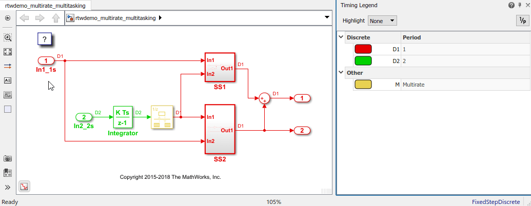
Sample times for Inport blocks
In1_1sandIn2_2sare set to 1 and 2 seconds, respectively.To provide a clear partitioning of rates, sample times for subsystems
SS1andSS2are set to 1.The Rate Transition block models an explicit rate transition. Alternatively, instruct Simulink to insert Rate Transition blocks for you by selecting model configuration parameter Automatically handle rate transition for data transfer.
Relevant Model Configuration Parameter Settings
Type set to
Fixed-step.Solver set to
discrete (no continuous states).Treat each discrete rate as a separate task selected.
Scheduling
Simulink® simulates the model based on the model configuration. Code that this model generates implements the same execution semantics. Simulink propagates and uses the Inport block sample times to order block execution based on a single-core, multitasking execution platform.
For this model, the sample time legend shows an implicit rate grouping. Red represents the fastest discrete rate. Green represents the second fastest discrete rate. Yellow represents the mixture of the two rates.
The generated code schedules subrates in the model. In this example, the rate for Inport block In2_2s, the green rate, is a subrate. The generated code properly transfers data between tasks that run at the different rates.
Benefits of implicit rate grouping:
Simulink does not impose architectural constraints on the model. Create a model without imposing software architecture constraints within the model.
Your execution framework does not require details about underlying function scheduling and data transfers between rates. Therefore, the model interface requirements are simplified. The execution framework uses generated interface code to write input, call the model step function, and read output.
The code generator optimizes code across rates based on multitasking execution semantics.
Simulink enforces data transfer constraints to achieve rate-monotonic scheduling:
Data transfers occur between a single read task and a single write task.
When data transfers between two tasks, only one task can preempt the other task.
For periodic tasks, a task with a faster rate has a higher priority than a task with a slower rate. In addition, a task with the faster rate, preempts a task with a slower rate.
Tasks run on a single processor.
Time slicing, use of a defined time period during which a task can run in a preemptive multitasking system, is not allowed.
Processes do not crash and restart, especially during data transfers between tasks.
Read and write operations on byte-sized variables are atomic.
Your execution framework communicates with external devices for reading and writing model input. For example, model external devices by using Simulink S-Function blocks. Generate code for those blocks with the rest of the algorithm.
Generate Code and Report
Open the Embedded Coder app. Then, generate code and a code generation report. The example model generates a report.
Review Generated Code
From the code generation report, review the generated code.
ert_main.cis an example main program (execution framework) for the model. This code controls model code execution by calling the entry-point functionsMultirateMultitasking_step0andMultirateMultitasking_step1. Use this file as a starting point for coding your execution framework.MultirateMultitasking.ccontains entry points for the code that implements the model algorithm. This file includes the rate scheduling code.MultirateMultitasking.hdeclares model data structures and a public interface to the model entry points and data structures.rtwtypes.hdefines data types, structures, and macros that the generated code requires.
Code Interface
Open and review the Code Interface Report. Use the information in that report to write the interface code for your execution framework:
Include the generated header file by adding directive
#include MultirateMultitasking.h.Write input data to the generated code for model Inport blocks.
Call the generated entry-point functions.
Read data from the generated code for model Outport blocks.
Input ports:
rtU.In1_1sof data typereal_Twith dimension of 1rtU.In2_2sof data typereal_Twith dimension of 1
Entry-point functions:
Initialization entry-point function,
void MultirateMultitasking_initialize(void). At startup, call this function once.Output and update entry-point (step) function,
void MultirateMultitasking_step0(void). Call this function periodically at the fastest rate in the model. For this model, call the function every second. To achieve real-time execution, attach this function to a timer.Output and update entry-point function,
void MultirateMultitasking_step1(void). Call this function periodically at the second fastest rate in the model. For this model, call the function every two seconds. To achieve real-time execution, attach this function to a timer.
Output ports:
rtY.Out1of data typereal_Twith dimension of 1rtY.Out2of data typereal_Twith dimension of 1