Hall Sensor Sequence Calibration for STM32G4xx Based Processors
This example shows how to control a BLDC motor by calculating the Hall sensor sequence with respect to position zero of the rotor in open-loop control. By using this method, you can use six-step commutation to control the motor without the need to label the Hall sensors or derive the switching sequence. Run this example on STM32G4xx Based Processors and obtain the Hall sequence, and use this Hall sequence with the Six Step Commutation (Motor Control Blockset) block to run the motor in closed-loop as explained in the Six-Step Commutation of BLDC Motor Using Hall Sensor Feedback for STM32G4xx Based Processors example. The Hall sequence calibration algorithm drives the motor through a full mechanical revolution and computes the Hall sensor sequence relative to the rotor's position zero in open-loop control.
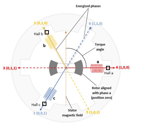
A Hall effect sensor varies its output voltage based on the strength of the applied magnetic field. In the standard configuration, a brushless DC (BLDC) motor consists of three Hall sensors located 120 electrical degrees apart. This arrangement provides six valid combinations of binary states: 001, 010, 011, 100, 101, and 110. The sensor outputs the rotor's angular position in 60-degree multiples, which the controller uses to determine the rotor's current 60-degree sector.
The target model runs the motor at a low speed (10 RPM) in open-loop control and performs V/f control on the motor. At this speed, the D-axis of the rotor closely aligns with the rotating magnetic field of the stator. Once the Hall sequence with respect to rotor zero is obtained, use this Hall sequence with Six Step Commutation (Motor Control Blockset) block. Ensure you use the same Hall sequence order obtained in this example when applying the Six-Step Commutation of BLDC Motor Using Hall Sensor Feedback for STM32G4xx Based Processors example to run the motor in closed-loop control.
When the rotor reaches the open-loop position zero, it aligns with the phase A-axis of the stator. At this position, corresponding to the Hall state, the six-step commutation algorithm energizes the next two stator phases, ensuring the rotor maintains a torque angle (angle between the rotor D-axis and the stator magnetic field) of 90 degrees with a deviation of 30 degrees. Use Six Step Commutation (Motor Control Blockset) block and the Hall sequence obtained from this workflow.
Note: This example works for any motor-phase or Hall sensor connection configuration.
Required Hardware
The example supports these hardware configuration. You can also use the target model name to open the model for the corresponding hardware configuration, from the MATLAB® command prompt. STM32G431RB Nucleo Board + X-Nucleo-IHM08M1 inverter: stm32_hall_sequence_calibration_target.slx
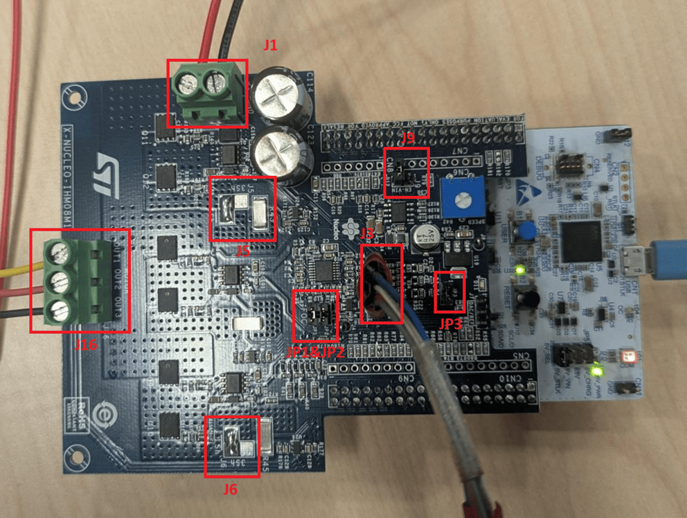
Jumper Name | Description | Status |
|---|---|---|
J1 | DC power supply | |
JP3 | Hall sensor | |
JP1 & JP2 | Closed | |
J5 & J6 | Soldered across the 1Sh pads | |
J9 | Open | |
J16 | Motor phase connections |
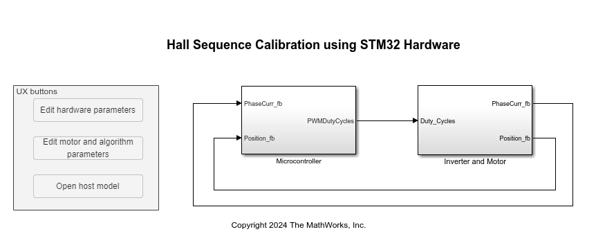
Models
The example includes these models:
You can use these models only for code generation.
Generate Code and Deploy Model to Target Hardware
This section shows you how to generate code and run the motor by using open-loop control. The example uses a host and a target model. The host model is a user interface to the controller hardware board. You can run the host model on the host computer. The prerequisite to use the host model is to deploy the target model to the controller hardware board.
The host model uses serial communication to command the target model and run the motor in an open-loop configuration by using V/f control. The host model displays the calculated Hall sensor sequence.
1. Complete the hardware connections as described in the required hardware section.
2. Open the target model for the hardware configuration that you want to use. If you want to change the default hardware configuration settings for the target model, see Model Configuration Parameters for STM32 Processor Based Boards.
3. Click Build, Deploy & Start on the Hardware tab to deploy the target model to the hardware.
4. Click the host model hyperlink in the target model to open the associated host model.
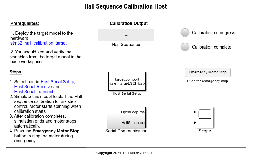
You can use the Scope block in the host model to monitor the open-loop rotor position and Hall sequence values.
7. In the host model, open the blocks Host Serial Setup, Host Serial Receive, and Host Serial Transmit, and select a Port.
8. Click Run on the Simulation tab to run the host model and start Hall sequence calibration for six-step commutation control. The motor runs and calibration begins when you start simulation. After the calibration process is complete, simulation ends and the motor stops automatically. If the motor does not start or rotate smoothly, increase the Vd Ref in Per Unit voltage value (maximum value is 1) in the Configuration panel. However, if the motor draws a high current, reduce this value.
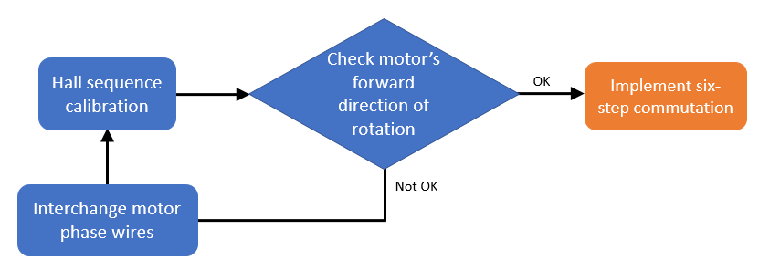
Six-step commutation control conventionally uses a forward direction of rotation that is identical to the direction of rotation used during Hall sequence calibration. To change the forward direction convention, interchange the motor phase wires, perform Hall sequence calibration again, and then run the motor by using six-step commutation control.
Note: This example does not support simulation.
To immediately stop the motor during an emergency, click the Emergency Motor Stop button.