Migrate PWM Output Block Usage to STM32 Processor Based Library Block
When you migrate PWM Output block usage in STMicroelectronics hardware board models from using Simulink Coder support package blocks to using Embedded Coder support package blocks, there is a workflow you should use. This table lists the blocks that should be migrated with this workflow.
Migrate Block Usage
Migrate from Blocks in Simulink Coder Support Package for STMicroelectronics Nucleo Boards Library | Migrate to Blocks in Embedded Coder Support Package for STMicroelectronics STM32 Processor Library |
|---|---|
To migrate your model from using these blocks to using the corresponding blocks in an STM32Fxx Based Board block library, follow these steps. These example steps show the process for migrating usage from the Nucleo library PWM Output block to the STM32 processor library PWM Output block:
Open the Simulink model in which you are migrating block usage.
From Configuration Parameters > Hardware Implementation, note that the Hardware board selection is
STM32 Nucleo F767ZI. Note the pin selections for SCL (D15corresponds to external pinPB_8) and SDA (D14corresponds to external pinPB_9).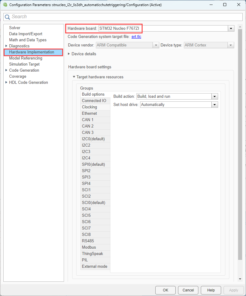
Change Hardware board selection to
STM32F4xx
            Based
. After the dialog box updates to match this selection, From Target hardware resources > Build options, use the Browse or Create buttons to select anSTM32CubMX project file.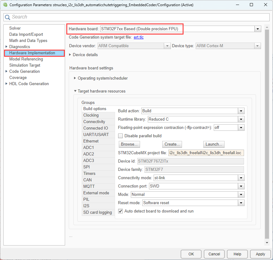
There are some additional options that you can configure for this timer resource.

To open the STM32 CubeMX configuration software and configure pin selections, click the Launch button from the Build options group.
In the STM32 CubeMX configuration software, configure the
TIM1resource for PWM operation on pinsPE9(TIM1_CH1) andPE11(TIM1_CH2).
Also, in the CubeMX configuration software, configure the settings for the counter and PWM generation.

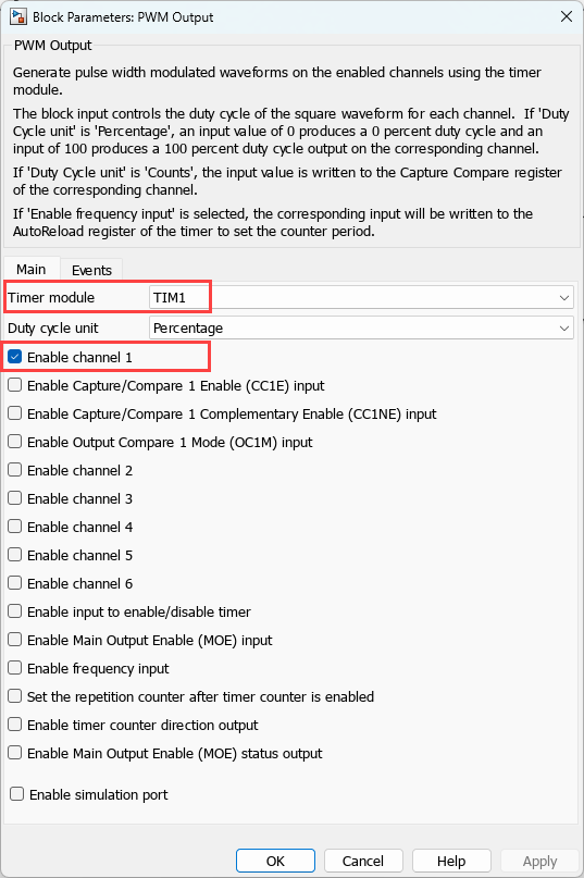
In the Simulink model, replace the PWM Output from the Nucleo library with a PWM Output from the STM32F7xx Based Boards library.
View the block configuration parameters. Confirm that the Timer module selection is configured for the default Timer module which is
TIM1and the channel is enabled. This setting matches the pin mapping that you assigned in the CubeMX configuration IOC file.