Migrate CAN Block Usage to STM32 Processor Based Library Block
When you migrate CAN block usage in STMicroelectronics hardware board models from using Simulink Coder support package blocks to using Embedded Coder support package blocks, there is a workflow you should use. This table lists the blocks that should be migrated with this workflow.
Block Usage Migrations
Migrate from Blocks in Simulink Coder Support Package for STMicroelectronics Nucleo Boards Library | Migrate to Blocks in Embedded Coder Support Package for STMicroelectronics STM32 Processor Library |
|---|---|
To migrate your model from using these blocks to using the corresponding blocks in an STM32Fxx Based Board block library, follow these steps. These example steps show the process for migrating usage from the Nucleo library CAN Receive block and CAN Transmit block to the STM32 processor library CAN Read block and CAN Write block:
Open the Simulink model in which you are migrating block usage.
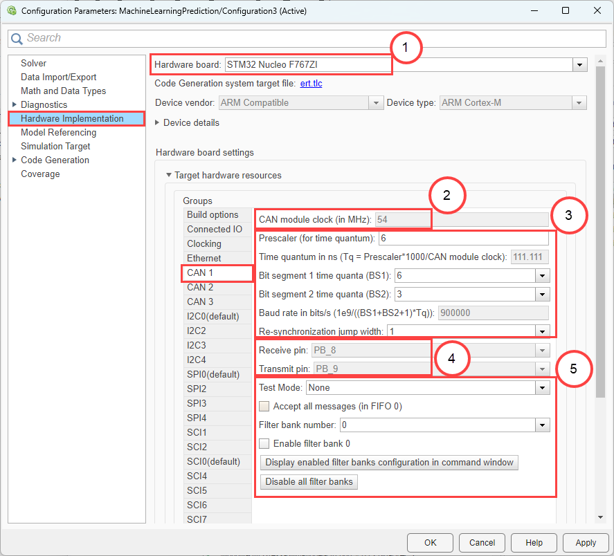
From Configuration Parameters > Hardware Implementation, note that the Hardware board selection is
STM32 Nucleo F767ZI. Note the Target hardware resource configuration for the CAN 1 resource. Later in this procedure, this information is needed for selections in the STM32 CubeMX configuration software.CAN module clock speed (2)
CAN module clock options (3)
CAN module pinout (4)
CAN module message option (5)
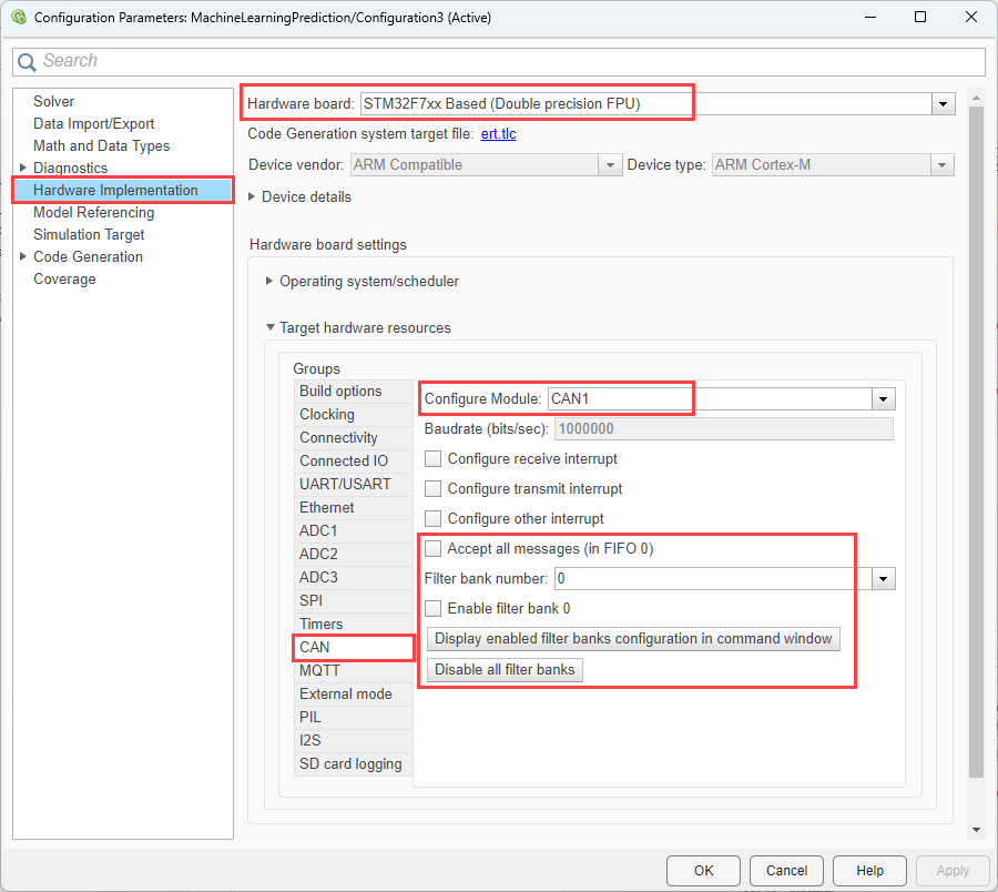
Change Hardware board selection to
STM32F7xx Based
            (Double precision FPU)
. After the dialog box updates to match this selection, From Target hardware resources > Build options, use the Browse or Create buttons to select anSTM32CubMX project file.From Target hardware resources > CAN, you can set additional options for the CAN resource.
In the Simulink model, replace the CAN Receive block and the CAN Transmit block from the Nucleo library with a CAN Read block and a CAN Write block from the STM32F7xx Based Boards library.
Open the block parameters dialog box for the blocks that you replace. In the replaced blocks, some block parameters have different options. These include:
Module: Module 1 corresponds to CAN 1, Module 2 to CAN 2, and so on.
Operation Mode: This parameter can be configured to Data, Read sleep status, and Read last error code.
Output receive: This parameter can be configured to indicate how full the FIFO is after a message is read. The maximum FIFO level is 3.
Timeout: This parameter can be configured, with the default set to 0.001.
To open the STM32 CubeMX configuration software and configure pin selections, click the Launch button from the Build options group.
In the STM32 CubeMX configuration software, configure the
Clock
            Configuration
resource for CAN protocol communication. For configuring the CAN module clock (measured in MHz), it is crucial to identify the specific peripheral connection, for that refer reference manual. In this example for STM32F767ZI, the CAN module is linked to the APB1 peripheral clocks. Make sure to input the correct clock value in the configuration settings for the CAN module. For detailed guidance on setting the correct clock value, refer to the CAN Bit Timing Guide.
Map these options directly in the STM32 CubeMX configuration:
Prescaler: Determines the division factor for the time quantum.
Time Quantum: Expressed in nanoseconds (ns), this is the basic unit of time used in CAN communication.
Bit Segment 1 (BS1): Specifies the number of time quanta in the first segment of a bit.
Bit Segment 2 (BS2): Defines the number of time quanta in the second segment of a bit.
Resynchronization Jump Width (RJW): The maximum number of time quanta by which the bit timing can be adjusted to maintain synchronization.

Configure the CAN transmit and receive pin connections to
PB9andPB8.