Control Onboard LED Brightness Using PWM Blocks on Renesas RA Microcontrollers
R2026bThis example shows how to control the brightness of an onboard LED on a Embedded Coder ® Support Package for Renesas® RA Microcontrollers by varying the duty cycle of a hardware PWM signal generated using the General PWM Timer (GPT). The example demonstrates how duty-cycle modulation directly affects LED intensity and how a Simulink model can be deployed to Renesas RA hardware for real-time execution.
You can use this workflow to validate PWM configuration, understand duty-cycle–based brightness control, or other PWM-controlled actuators on Renesas RA devices.
The example shows how to:
Generate a hardware PWM signal using the GPT32 peripheral.
Control LED brightness by varying the PWM duty cycle using an interactive slider input.
Deploy a Simulink model to Renesas RA hardware and observe real-time behavior.
Prerequisites
Before you begin,
Complete these tutorials:
Review the MCK-RA6T2 User's Manual.
Complete the Hardware Setup for Embedded Coder Support Package for Renesas RA Microcontrollers.
Required Hardware
USB Cable
Jumper wire
FTDI Friend (For example FTDI Friend USB TTL-232R 3.3V adapter).
Hardware Connections
This example uses LED2 on the MCK-RA6T2 board.
Use a jumper wire to route the PWM output pin PB04 to LED2 (PD02) on the 1st Inverter Board Connector (CN5).
When using an FTDI adapter for communication between the host computer and the Renesas RA6T2 target board, make the following connections.
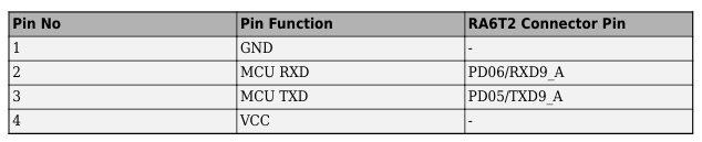
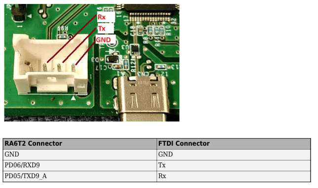
The Rx, Tx, and GND labels shown in red in the figure indicate the corresponding pins on the FTDI connector.
RASC Project File
This example uses a Renesas Smart Configurator (RASC) project file to define the hardware configuration required for PWM generation.
The RASC project file contains:
GPT timer configuration for PWM operation.
Output pin mapping for the onboard LED.
Clock and peripheral settings required by the PWM block.
Configure the Simulink Model
Open the PWMExampleModelRA6.slx Simulink model.
modelName = "PWMExampleModelRA6";
open_system(modelName)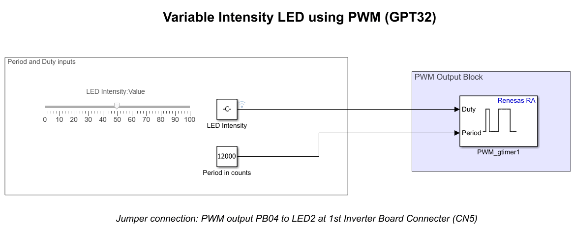
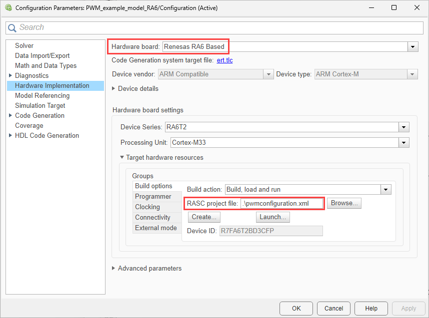
The model is pre-configured for Renesas RA6 Based hardware.
Ensure the following settings are applied:
configuration.xmlis added as the Renesas Smart Configurator (RASC) project file in Build options. To verify click Modeling > Model Settings to open the Configuration Parameters dialog box. Navigate to Hardware Implementation > Target hardware resources > Build options.
Configure the Blocks
Period and Duty Inputs
The Period and Duty inputs area defines the PWM behavior:
A Constant block specifies the PWM period (for example, 12000 counts).
A Slider dashboard control (range 0–100) allows you to interactively adjust LED intensity. A Constant block labeled LED Intensity passes the slider value to the Duty input of the PWM Output block.
LED Brightness Behavior
Increasing the duty cycle increases the average on-time of the PWM signal.
Increased on-time raises the average current through the LED.
Higher average current results in increased perceived LED brightness.
Reducing the duty cycle dims the LED accordingly.
Varying the PWM duty cycle gradually changes the LED brightness.
PWM Output Block
The PWM_gtimer1 block generates the hardware PWM signal using the GPT32 peripheral.
The Duty input port controls the duty cycle based on the LED intensity input.
The Period input port specifies the PWM period in timer counts.
The output pin drives the onboard LED.
Deploy Model to Hardware
Deploy the model to the target hardware and observe how PWM duty-cycle changes affect LED brightness in real time.
To deploy and run the model:
1. In the Simulink toolstrip, from the Hardware tab, click Build, Deploy & Start. This action generates code, programs the target, and starts execution on the Renesas RA6 board.

Click Build, Deploy & Start. This action generates code, programs the target, and starts execution on the Renesas RA6 board.Alternatively, run the
Click Monitor & Tune to run the model in External mode. This action builds and deploys the model, connects Simulink to the target hardware, and enables you to monitor and tune parameters in External mode during execution.
2. To monitor progress, open the Diagnostic Viewer using the link displayed at the bottom of the model canvas. The Diagnostic Viewer reports code generation, compilation, and download status.
Observe LED Brightness Behavior
Observe the onboard LED on the Renesas RAMCK-RA6T2 board. Use the Slider control to adjust the LED intensity in real time. Moving the slider changes the duty cycle, which varies the brightness of LED2 on the board.

