Implement Orientation-Based LED Control Using I2C Communication on Infineon AURIX TC3x Microcontrollers
R2026bThis example shows how to read an MPU6050 accelerometer sensor data over Inter-Integrated Circuit (I2C) communication protocol. The example also shows how to indicate the sensor orientation by blinking LEDs connected to the general purpose input output (GPIO) pins of an Infineon® AURIX™ TC3x hardware board.
The example uses I2C controller write block created using the IO Device Builder application. For more information on using the IO Device Builder application for driver blocks creation, see Get Started with IO Device Builder.
Required Hardware
Infineon AURIX TC3x hardware board
MPU6050 accelerometer sensor
Hardware Connection
The AURIX Microcontroller operates as the I2C controller and the MPU6050 operates as the I2C peripheral. The controller generates the clock signal on the SCL line and exchanges data with the sensor over the SDA line to read acceleration and angular velocity measurements.
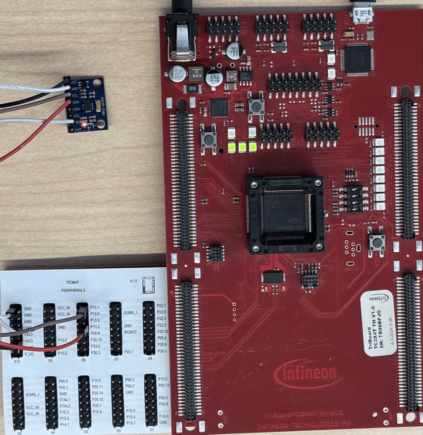
Connect the MPU6050 sensor to the Infineon AURIX microcontroller as shown in the table. After completing the connections, power the AURIX TriBoard and connect it to the development computer using a USB cable.
MPU6050 pin | Infineon AURIX TriBoard pin | Description |
|---|---|---|
VCC | 3.3 V supply | Powers the sensor using the 3.3 V supply from the board. |
GND | GND | Provides a common ground reference between the sensor and the board. |
SCL | P13.1 | Carries the I2C clock signal generated by the microcontroller. |
SDA | P13.2 | Carries the bidirectional I2C data signal to exchange the sensor data. |
AD0 | GND | Configures the sensor for the default I2C address 0x68. The microcontroller uses this address to identify and communicate with the sensor on the I2C bus. |
Model Description
Open the tc3x_LedBlinky_mpu6050_I2CReadRegisterAccess model.
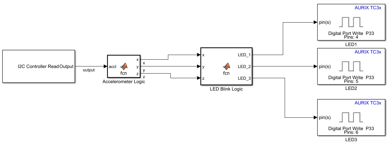
The model is pre-configured for Infineon AURIX TC3x microcontrollers and it contains four main stages:
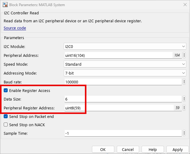
Sensor data acquisition ― The I2C Controller Read block reads raw bytes from the MPU6050 sensor over an I2C interface. To perform the required register write and read operations in a single step, select the Enable Register Access parameter of this block. Set Data Size and Peripheral Register Address parameters to
6and uint8(59).
Accelerometer data processing ― The Accelerometer Logic subsystem converts the raw MPU6050 accelerometer data into acceleration values along the x, y, and z-axes.
Orientation detection ― The LED Blink Logic subsystem determines the sensor board orientation from the acceleration measurements. When the sensor is stationary, gravity acts primarily along one axis. The subsystem compares the acceleration magnitudes on the x, y, and z-axes, identifies the dominant axis, and activates the corresponding LED. It activates LED1 for left or right tilt, LED2 for forward or backward tilt, and LED3 when the board is flat.
LED control ― Three Digital Port Write blocks drive LEDs connected to the GPIO pins P13.0, P13.1, and P13.2 on the AURIX TC3x Microcontrollers. Each block toggles an LED according to the orientation logic output, providing a visual indication of the board orientation.
Generate Code and Deploy on Hardware
Open the tc3x_LedBlinky_mpu6050_I2CReadRegisterAccess model.
Complete the hardware connections.
To generate code and deploy, in the Simulink editor, on the Hardware tab, click Build, Deploy & Start. The build process generates the binary executable files.
To monitor signals from the hardware, download and install the One Eye tool. Before using the One Eye tool, download and install the latest version of the Tool Access Software/Device Access Server (TAS/DAS) tool.
Open the One Eye tool and click File. To load the OneEye configuration file included in the example, click Load Configuration and select
tc3x_LedBlinky_mpu6050_I2C.OneEyefile.To load the executable and linkable format (ELF) file generated in step 3, in the Debug box viewer pane, click Load ELF file. Select
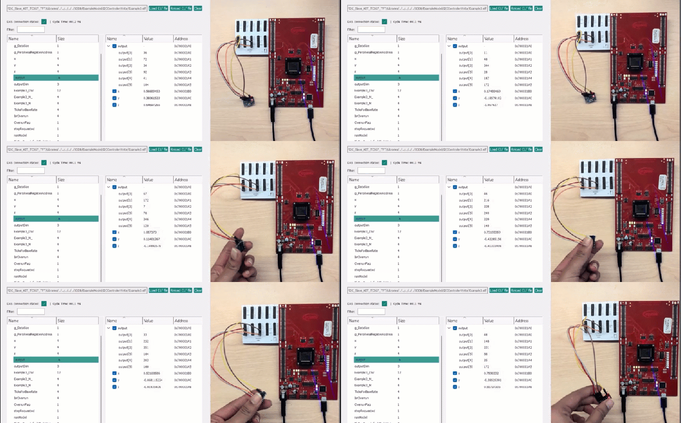
tc3x_LedBlinky_mpu6050_I2CReadRegisterAccess.elf.Rotate the MPU6050 sensor and observe that the LEDs on the hardware board blink based on the sensor orientation.
Other Things to Try
The example model uses the I2C Controller Read block with the Enable register access parameter enabled to perform register write and read operations in a single step. Alternatively, you can use separate I2C Controller Write and I2C Controller Read blocks. The example also includes the tc3x_LedBlinky_mpu6050_I2CReadWriteBlocks model and tc3x_LedBlinky_mpu6050_I2CReadWrite.OneEye configuration file, which demonstrates this approach. Use this model and OneEye configuration file to verify the sensor orientation detection and the corresponding LED blink pattern.

