Model Configuration Parameters
Update the configuration parameters for a Simulink® model that you create, before simulating or deploying the model to the controller.
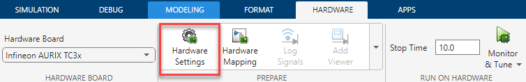
In the Simulink window, click Hardware Settings in the HARDWARE tab to open the Configuration Parameters dialog box and select the target hardware in the Hardware board field. You can also press Ctrl+E to open the Configuration Parameters dialog box.
Hardware Implementation Pane Overview

Configure hardware board to run Simulink models.
In the Simulink Editor, select Simulation > Model Configuration Parameters.
In the Configuration Parameter dialog box, click Hardware Implementation.
Set the Hardware board parameter to
Infineon AURIX TC3x.The parameter values under Hardware board settings are automatically populated to their default values.
You can optionally adjust these parameters for your particular use case.
To apply the changes, click Apply.
Design Mapping
The Hardware Mapping tool allows you to configure the software tasks and peripherals on the selected hardware board.
In this tool, you can map the tasks in your software model to the available event sources and interrupts. The sources of events or interrupts depend on the choice of hardware board and peripherals available in the model.
In this tool, you can configure the peripheral by setting hardware specific parameters. The available parameters depend on the selected hardware board for the model and the peripheral.
For more information, see Hardware Mapping.
Target hardware resources
Device
| Parameter | Description | Default Value |
|---|---|---|
| Series | Displays the device series for the selected hardware board. |
|
| Step | Displays the device step for the selected hardware board. |
|
| Package type | Displays the device packaging type for the selected hardware. |
|
| Package class | Displays the number of programmable pins for the selected hardware board/microcontrollers. |
|
Build Options
| Parameter | Description | Default Value |
|---|---|---|
| Build action | Define how Embedded Coder® responds when you build your model. |
|
| Disable parallel build | Select to compile the generated code and driver source codes in parallel order for faster build and deployment speed. | off |
| Enable force rebuild of static library | Select to force rebuild of the static driver library. |
|
| Enable program cache # | Select the program cache. |
|
| Enable data cache # | Select the data cache. |
|
Clocking
| Parameter | Description | Default Value |
|---|---|---|
| External oscillator (MHz) | Oscillator frequency used in the processor. |
|
| CPU Clock (MHz) | CPU clock frequency of the microcontrollers on the target hardware |
|
Connectivity
| Parameter | Description | Default Value |
|---|---|---|
| Connectivity interface | Select the type of communication interface for simulation. | Serial (ASCLIN0) |
| Port | Select the serial communication interface module. | empty |
| Baud rate | Select the baud rate of the serial communication port. | 921600 |
External mode
| Parameter | Description | Default Value |
|---|---|---|
| Communication interface | Select the transport layer External mode uses to exchange data between the host computer and the target hardware | Serial |
| Verbose | Select Verbose to view the External mode execution progress and updates. | off |