Generate and Verify HDL Code with DSP HDL IP Designer App
This example shows how to configure and generate HDL code for an FIR filter using the DSP HDL IP Designer app, and also generate testbenches to verify the HDL code.
To generate an HDL IP core for an algorithm in the DSP HDL IP Designer app, follow these steps:
Select an algorithm and set its parameters.
Configure input dimensions and data types.
Generate HDL code and testbenches.
You can use the app to optionally generate any of these testbenches:
HDL testbench that verifies generated code against captured data vectors from a MATLAB® simulation
Cosimulation testbench that runs in MATLAB, launches an HDL simulator, and compares the HDL simulation results against simultaneous simulation in MATLAB
SystemVerilog DPI-C component that you can use as a golden reference model and integrate into a larger verification environment
Open the App
In the Apps gallery, under the Signal Processing and Audio group, click the DSP HDL IP Designer app. Alternatively, at the MATLAB command prompt, enter this command:
dsphdlIPDesigner
This example includes the app-gsfir-ex.mat file, which contains the settings for the filter design. To load these settings in the app, click New Session and open this file.
Select Algorithm
While this example shows a fully parallel FIR filter design, the app enables you to explore other filter implementation options. For details, see FIR Filter Architectures for FPGAs and ASICs.
From the IP Blocks gallery in the app, select the Discrete FIR Filter.
Each IP block in the app provides the same implementation, ports, and parameters as the Simulink® library block for the same algorithm. For information about the ports and parameters of each algorithm, see the block reference pages. For example, see Discrete FIR Filter.

All the algorithms have streaming interfaces with a data port and a control signal that indicates when the input data is valid. The data ports accept and return a scalar or small vector of input data samples on each clock cycle. In the app, you can see the interface signals connecting the IP block to the Input Stimulus block. The IP block displays the latency for this configuration of the algorithm.
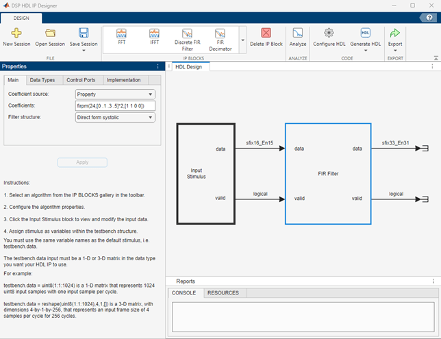
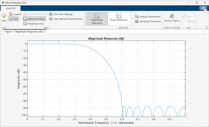
To configure your algorithm, set options in the Properties sidebar. Setting the Filter Structure parameter to Direct form systolic implements a fully parallel filter with high throughput. Configure the filter coefficients as a 25-tap lowpass FIR filter by setting the Coefficients parameter to firpm(24,[0 .1 .3 .5]*2,[1 1 0 0]).
To open the Filter Analyzer tool and see the magnitude response of the filter, click the Analyze button.
In the DSP HDL IP Designer app, set the data types of the coefficients and outputs on the Data Types tab. By default, the coefficients data type is set to Same word length as input, or you can customize the data type by specifying a numerictype function call. The default output data type is Full precision.
Configure Input Stimulus
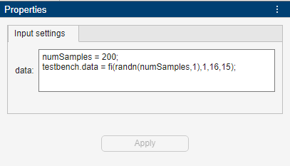
Click the Input Stimulus block. The Input settings section in the Properties sidebar provides dimensions and data types for the input to the algorithm. The app provides default values for each input port. The dimensions and data types of these values define your HDL interface, and the generated testbench applies these values to your algorithm. You do not need to specify values for control signals like valid and reset. The generated testbench automatically drives the control signals. For this algorithm, you must specify the data input.
The data input for an algorithm can be a 1-D or 3-D matrix. A 1-D matrix represents a stream of data samples over time. A 3-D matrix represents number of input samples per cycle-by-number of data channels-by-data samples over time.
This example specifies a 1-D matrix that represents 200 fixed-point data type input samples. This data format configures the filter to accept one input sample each clock cycle and the filter has a single data channel.
numSamples = 200;
testbench.data = fi(randn(numSamples,1),1,16,15);
For more examples of input configuration, see Setting Input Stimulus.
Generate HDL Code and Testbenches
You can configure HDL code generation options in Configure HDL. By default, the app generates an HDL simulator testbench and scripts for compiling and running the design in the Siemens® ModelSim® and AMD® Vivado® simulators. The HDL simulator testbench applies the input signals you defined in Input Stimulus, drives the input control signals, and compares all the output ports of the generated HDL IP block against the output from running your algorithm in a MATLAB simulation.
To generate HDL code and a testbench, click Generate HDL. The code generation log appears in the Console window, including any warning or error messages.
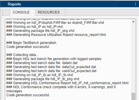
The generated files and reports are under codegen\hdl_IP\hdlsrc in your working folder. You can find more information about any errors or warnings in the hdl_IP_hdl_conformance_report.html file.
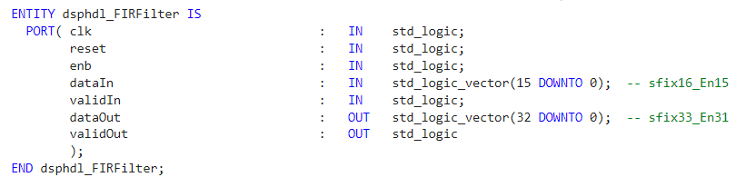
The generated VHDL® entity shows the IP block interface, including control signals and the data types that you specified.
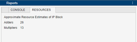
The Resources tab shows an estimate of hardware resources that this filter implementation uses. A filter with scalar input shares multipliers between symmetric coefficients, so this 25-tap filter uses 13 multipliers.
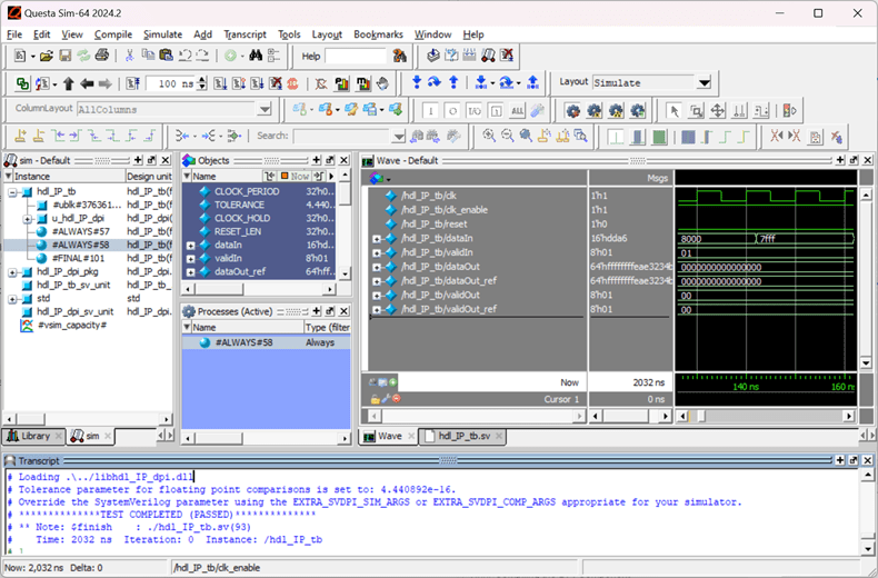
HDL Testbench
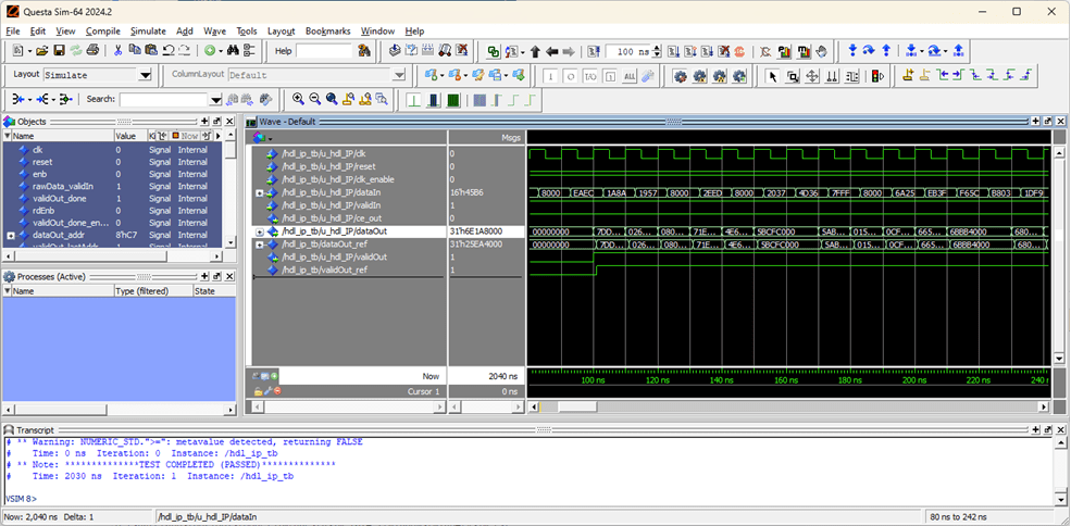
Open the ModelSim simulator and navigate to the codegen\hdlsrc folder. To compile and simulate the generated HDL testbench, at the command prompt in ModelSim, run the generated hdl_IP_tb_compile.do and hdl_IP_tb_sim.do scripts. The output data matches the expected reference data and the testbench passes with no errors.
%vsim> do hdl_IP_tb_compile.do
%vsim> do hdl_IP_tb_sim.do
Cosimulation Testbench
A cosimulation testbench runs your generated HDL code in the HDL simulator alongside a MATLAB simulation of your design. The MATLAB testbench includes stimulus generation, a behavioral model of the FIR filter, and live comparison of the HDL cosimulation output against the behavioral output. Compared to the test vector approach of the HDL testbench, a cosimulation testbench allows more comprehensive verification. You can easily modify the input stimulus and run the cosimulation testbench to cover different test cases.
To generate a cosimulation testbench, in the Configure HDL options, on the Cosimulation tab, select Generate cosimulation testbench. Also, select your HDL simulator. This example uses ModelSim and opens the HDL simulator in GUI mode.

When you click Generate HDL, the app generates the cosimulation testbench. The testbench generation log and any warnings or errors from generation appear in the Console window.
To simulate the cosimulation testbench, in the MATLAB command window, call the generated run_hdl_IP_cosim script. In the simulation output, look for these messages:
### Launching ModelSim for cosimulation
### Waiting for ModelSim to start
### Simulating generated test bench
### Finished Simulation
If the outputs from the generated HDL code and the MATLAB simulation do not match, the simulation shows error messages before Finished Simulation.
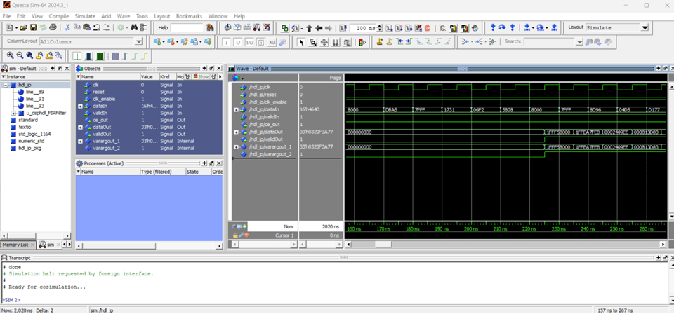
After simulation of the cosimulation testbench, you can view the waves in ModelSim.
SystemVerilog DPI Component
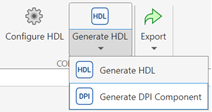
One way to integrate a behavioral model of your algorithm into a larger testbench is to use a SystemVerilog DPI-C component. This component simulates the behavior of your algorithm so you can verify the generated HDL design against this model. To generate this component, click the arrow on the Generate HDL button and click Generate DPI Component.
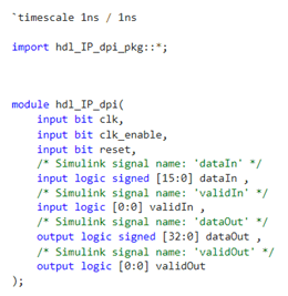
The generated DPI components and associated files are in the codegen/dll/hdl_IP folder. The generated DPI module in the hdl_IP_dpi.sv file shows the interface of your algorithm.
The app also generates a testbench that compares the generated DPI-C component with the MATLAB simulation of your algorithm, and the scripts to run the testbench in various HDL simulators. Open ModelSim and navigate to the codegen/dll/hdl_IP/dpi_tb folder. In ModelSim, run the generated testbench. This testbench verifies that the output of the SystemVerilog DPI component matches the expected test vectors from the MATLAB simulation of your algorithm.
%vsim> do run_tb_mq.do