Multilevel Filter Banks
Multirate filters alter the sample rate of the input signal during the filtering process. Such filters are useful in both rate conversion and filter bank applications.
The Dyadic Analysis Filter Bank block decomposes a broadband signal into a collection of subbands with smaller bandwidths and slower sample rates. The Dyadic Synthesis Filter Bank block reconstructs a signal decomposed by the Dyadic Analysis Filter Bank block.
To use a dyadic synthesis filter bank to perfectly reconstruct the output of a dyadic analysis filter bank, the number of levels and tree structures of both filter banks must be the same. In addition, the filters in the synthesis filter bank must be designed to perfectly reconstruct the outputs of the analysis filter bank. Otherwise, the reconstruction will not be perfect.
Dyadic Analysis Filter Banks
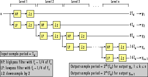
Dyadic analysis filter banks are constructed from the following basic unit. The unit can be cascaded to construct dyadic analysis filter banks with either a symmetric or asymmetric tree structure.

Each unit consists of a lowpass (LP) and highpass (HP) FIR filter pair, followed by a decimation by a factor of 2. The filters are halfband filters with a cutoff frequency of Fs / 4, a quarter of the input sampling frequency. Each filter passes the frequency band that the other filter stops.
The unit decomposes its input into adjacent high-frequency and low-frequency subbands. Compared to the input, each subband has half the bandwidth (due to the half-band filters) and half the sample rate (due to the decimation by 2).
Note
The following figures illustrate the concept of a filter bank, but not how the block implements a filter bank; the block uses a more efficient polyphase implementation.
n-Level Asymmetric Dyadic Analysis Filter Bank

Use the above figure and the following figure to compare the two tree structures of the dyadic analysis filter bank. Note that the asymmetric structure decomposes only the low-frequency output from each level, while the symmetric structure decomposes the high- and low-frequency subbands output from each level.
n-Level Symmetric Dyadic Analysis Filter Bank

The following table summarizes the key characteristics of the symmetric and asymmetric dyadic analysis filter bank.
Notable Characteristics of Asymmetric and Symmetric Dyadic Analysis Filter Banks
| Characteristic | N-Level Symmetric | N-Level Asymmetric |
|---|---|---|
Low- and High-Frequency Subband Decomposition | All the low-frequency and high-frequency subbands in a level are decomposed in the next level. | Each level's low-frequency subband is decomposed in the next level, and each level's high-frequency band is an output of the filter bank. |
Number of Output Subbands | 2n | n+1 |
Bandwidth and Number of Samples in Output Subbands | For an input with bandwidth BW and N samples, all outputs have bandwidth BW / 2n and N / 2n samples. | For an input with bandwidth BW and N samples, yk has the bandwidth BWk, and Nk samples, where The bandwidth of, and number of samples in each subband (except the last) is half those of the previous subband. The last two subbands have the same bandwidth and number of samples since they originate from the same level in the filter bank. |
Output Sample Period | All output subbands have a sample period of 2n(Tsi) | Sample period of kth output
Due to the decimations by 2, the sample period of each subband (except the last) is twice that of the previous subband. The last two subbands have the same sample period since they originate from the same level in the filter bank. |
Total Number of Output Samples | The total number of samples in all of the output subbands is equal to the number of samples in the input (due to the decimations by 2 at each level). | |
Wavelet Applications | In wavelet applications, the highpass and lowpass wavelet-based filters are designed so that the aliasing introduced by the decimations are exactly canceled in reconstruction. | |
Dyadic Synthesis Filter Banks
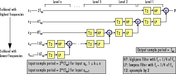
Dyadic synthesis filter banks are constructed from the following basic unit. The unit can be cascaded to construct dyadic synthesis filter banks with either a asymmetric or symmetric tree structure as illustrated in the figures titled 'n-Level Asymmetric Dyadic Synthesis Filter Bank' and 'n-Level Symmetric Dyadic Synthesis Filter Bank'.

Each unit consists of a lowpass (LP) and highpass (HP) FIR filter pair, preceded by an interpolation by a factor of 2. The filters are halfband filters with a cutoff frequency of Fs / 4, a quarter of the input sampling frequency. Each filter passes the frequency band that the other filter stops.
The unit takes in adjacent high-frequency and low-frequency subbands, and reconstructs them into a wide-band signal. Compared to each subband input, the output has twice the bandwidth and twice the sample rate.
Note
The following figures illustrate the concept of a filter bank, but not how the block implements a filter bank; the block uses a more efficient polyphase implementation.
n-Level Asymmetric Dyadic Synthesis Filter Bank

Use the above figure and the following figure to compare the two tree structures of the dyadic synthesis filter bank. Note that in the asymmetric structure, the low-frequency subband input to each level is the output of the previous level, while the high-frequency subband input to each level is an input to the filter bank. In the symmetric structure, both the low- and high-frequency subband inputs to each level are outputs from the previous level.
n-Level Symmetric Dyadic Synthesis Filter Bank

The following table summarizes the key characteristics of symmetric and asymmetric dyadic synthesis filter banks.
Notable Characteristics of Asymmetric and Symmetric Dyadic Synthesis Filter Banks
| Characteristic | N-Level Symmetric | N-Level Asymmetric |
|---|---|---|
Input Paths Through the Filter Bank | Both the high-frequency and low-frequency input subbands to each level (except the first) are the outputs of the previous level. The inputs to the first level are the inputs to the filter bank. | The low-frequency subband input to each level (except the first) is the output of the previous level. The low-frequency subband input to the first level, and the high-frequency subband input to each level, are inputs to the filter bank. |
Number of Input Subbands | 2n | n+1 |
Bandwidth and Number of Samples in Input Subbands | All inputs subbands have bandwidth BW / 2n and N / 2n samples, where the output has bandwidth BW and N samples. | For an output with bandwidth BW and N samples, the kth input subband has the following bandwidth and number of samples. |
Input Sample Periods | All input subbands have a sample period of 2n(Tso), where the output sample period is Tso. | Sample period of kth input subband where the output sample period is Tso. |
Total Number of Input Samples | The number of samples in the output is always equal to the total number of samples in all of the input subbands. | |
Wavelet Applications | In wavelet applications, the highpass and lowpass wavelet-based filters are carefully selected so that the aliasing introduced by the decimation in the dyadic analysis filter bank is exactly canceled in the reconstruction of the signal in the dyadic synthesis filter bank. | |
For more information, see Dyadic Synthesis Filter Bank.
See Also
Objects
dsp.SubbandAnalysisFilter|dsp.SubbandSynthesisFilter|dsp.DyadicAnalysisFilterBank|dsp.DyadicSynthesisFilterBank
Blocks
- Two-Channel Analysis Subband Filter | Two-Channel Synthesis Subband Filter | Dyadic Analysis Filter Bank | Dyadic Synthesis Filter Bank