Model Multirate Signal Processing Systems Using Dataflow
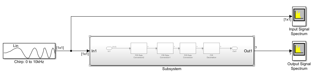
This example shows how to model multirate signal processing systems using the dataflow subsystem. When you set the domain of a subsystem to dataflow and enable the Automatic frame size calculation parameter, the software calculates the signal sizes of frame-based multirate models and inserts buffers so that the model compiles with no frame size propagation errors.
For more information on dataflow domains, see Dataflow Domain.
Use Dataflow to Resolve Frame Size Propagation Errors
When the model is initially simulated, the software generates an error due to a port dimension mismatch. To fix this error, set the domain of the subsystem to dataflow.

Configure Model for Dataflow Execution Domain
To configure a subsystem for dataflow execution domain:
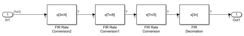
Open your model and open the subsystem. This model uses a Subsystem block with several rate transition conversion blocks to model a multirate signal processing system.
Set the domain of the subsystem to dataflow. If the Property Inspector is not visible, in the Modeling tab, under Design, select Property Inspector. With the subsystem selected, in the Execution tab of the Property Inspector, select Set execution domain. Set the Domain to
Dataflow.

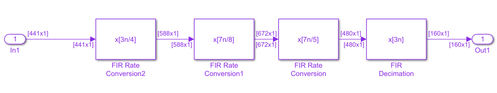
Observe that when Automatic frame size calculation is selected, the software automatically calculates frame sizes and inserts buffers where needed.
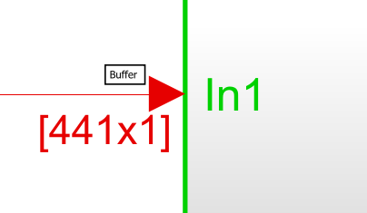
Badges on the model canvas at the input of the subsystem indicate where buffers are inserted.
To see the updated version of the model, open ex_multirate_filter.
Programmatically Configure Model for Dataflow Execution Domain
To configure the model programmatically, use the set_param function.
Open the model.
open_system('ex_multirate_filter.slx');Enable Set execution domain, and set the Domain to Dataflow.
set_param('ex_multirate_filter/Subsystem', 'SetExecutionDomain', 'on');
set_param('ex_multirate_filter/Subsystem', 'ExecutionDomainType', 'Dataflow');
Enable Automatic frame size calculation to have the software automatically calculate frame sizes and insert buffers where needed.
set_param('ex_multirate_filter/Subsystem', 'AutoFrameSizeCalculation', 'on');
To analyze the multicore execution behavior of a dataflow domain in Simulink, see Perform Multicore Analysis for Dataflow.