GSM Digital Down Converter in MATLAB
This example shows how to simulate steady-state behavior of a fixed-point digital down converter for GSM (Global System for Mobile) baseband conversions. The example uses signal processing System objects to emulate the operation of the TI Graychip 4016 Quad Digital Down Converter and requires a Fixed-Point Designer™ license.
Introduction
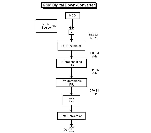
The Digital Down Converter (DDC) is an important component of a digital radio. It performs frequency translation to convert the high input sample rate down to a lower sample rate for efficient processing. In this example the DDC accepts a bandpass signal with a sample rate around 70 megasamples per seconds (MSPS) and performs the following operations:
Digital mixing or down conversion of the input signal using a Numerically Controlled Oscillator (NCO) and a mixer.
Narrowband low-pass filtering and decimation using a filter chain of Cascaded Integrator-Comb (CIC) and FIR filters.
Gain adjustment and final resampling of the data stream.
The DDC produces a baseband signal with a sample rate of 270 kilosamples per seconds (KSPS) that is ready for demodulation. A block diagram of a typical DDC is shown below.
if ~isfixptinstalled
    error(message('dsp:dspDigitalDownConverter:noFixptTbx'));
end
Initialization
Create and configure a sine wave source System object™ to model the GSM source. You set the object's frequency to 69.1e6*5/24 MSPS because, after digital mixing, the object will have a baseband frequency of around 48 KSPS. Because the system you are modeling resamples the input by a factor of 4/(3*256), you need to set the object's frame size to be the least common multiplier of these factors.
Fs = 69.333e6;
FrameSize = 768;
sine = dsp.SineWave( ...
            'Frequency', 69.1e6*5/24, ...
            'SampleRate', Fs, ...
            'Method', 'Trigonometric function', ...
            'SamplesPerFrame', FrameSize);
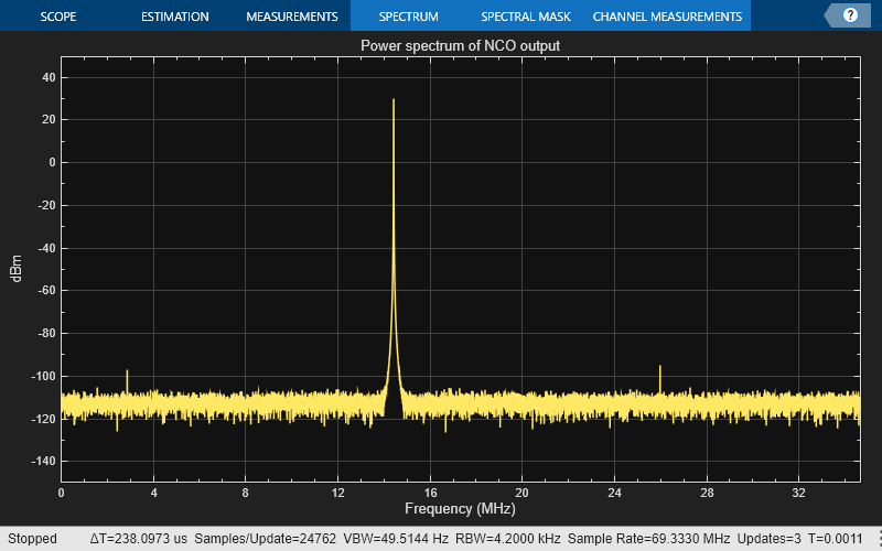
Create and configure an NCO System object to mix and down convert the GSM signal. The TI Graychip requires the tuning frequency (PhaseIncrement property) to be a 32-bit data type with 32-bit fraction length. The phase offset needs to be a 16-bit data type with 16-bit fraction length. To reduce the amplitude quantization noise and spread the spurious frequencies across the available bandwidth, add a dither signal to the accumulator phase values. Typically, the number of dither bits (14) is the difference between the accumulator word length (32) and the table address word length (18).
nco = dsp.NCO( ...
            'PhaseIncrementSource', 'Property', ...
            'PhaseIncrement', int32((5/24) *2^32), ...
            'PhaseOffset', int16(0), ...
            'NumDitherBits', 14, ...
            'NumQuantizerAccumulatorBits', 18, ...
            'Waveform', 'Complex exponential', ...
            'SamplesPerFrame', FrameSize, ...
            'AccumulatorDataType', 'Custom', ...
            'CustomAccumulatorDataType', numerictype([],32), ...
            'OutputDataType', 'Custom', ...
            'CustomOutputDataType', numerictype([],20,18));
Create and configure a CIC decimator System object that decimates the mixer output by a factor of 64. CIC filters can achieve high decimation or interpolation rates without using any multipliers. This feature makes them very useful for digital systems operating at high rates.
M1 = 64;
cicdec = dsp.CICDecimator( ...
            'DecimationFactor', M1, ...
            'NumSections', 5, ...
            'FixedPointDataType', 'Minimum section word lengths', ...
            'OutputWordLength', 20);
Create and configure an FIR decimator System object to compensate for the passband droop caused by the CIC filter. This filter also decimates by a factor of 2.
gsmcoeffs; % Read the CFIR and PFIR coeffs
M2 = 2;
cfir = dsp.FIRDecimator(M2, cfir, ...
            'CoefficientsDataType', 'Custom', ...
            'CustomCoefficientsDataType', numerictype([],16), ...
            'FullPrecisionOverride', false,...
            'OutputDataType', 'Custom', ...
            'CustomOutputDataType', numerictype([],20,-12));
Create and configure an FIR decimator System object to reduce the sample rate by another factor of 2.
M3 = 2;
pfir = dsp.FIRDecimator(M3, pfir, ...
            'CoefficientsDataType', 'Custom', ...
            'CustomCoefficientsDataType', numerictype([],16), ...
            'FullPrecisionOverride',false, ...
            'OutputDataType', 'Custom', ...
            'CustomOutputDataType', numerictype([],20,-12));
Create and configure an FIR rate converter System object to resample the final output by a factor of 4/3.
firrc = dsp.FIRRateConverter(4, 3, fir1(31,0.25),...
    'CoefficientsDataType', 'Custom', ...
    'CustomCoefficientsDataType', numerictype([],12), ...
    'FullPrecisionOverride',false, ...
    'OutputDataType', 'Custom', ...
    'CustomOutputDataType', numerictype([],24,-12));
Create a fi object of specified numerictype to act as a data type conversion for the sine output.
gsmsig = fi(zeros(768,1),true,14,13);
Create a fi object of specified numerictype to store the fixed-point mixer output.
mixsig = fi(zeros(768,1),true,20,18);
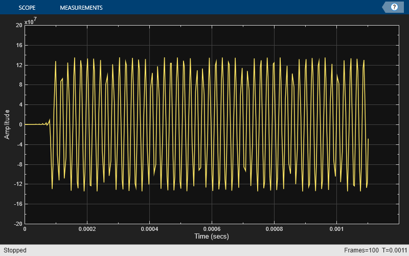
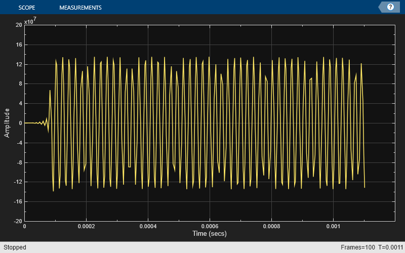
Create and configure two Time Scope System objects to plot the real and imaginary parts of the FIR rate converter filter output.
timeScope1 = timescope(...
  'Name', 'Rate Converter Output: Real Signal', ...
  'SampleRate', Fs/256*4/3, ...
  'TimeSpan', 1.2e-3, ...
  'YLimits', [-2e8 2e8], ...
  'TimeSpanOverrunAction', 'Scroll');
pos = timeScope1.Position;
timeScope1.Position(1:2) = [pos(1)-0.8*pos(3) pos(2)+0.7*pos(4)];

timeScope2 = timescope(...
  'Name', 'Rate Converter Output: Imaginary Signal', ...
  'Position', [pos(1)-0.8*pos(3) pos(2)-0.7*pos(4) pos(3:4)], ...
  'SampleRate', Fs/256*4/3, ...
  'TimeSpan', 1.2e-3, ...
  'YLimits', [-2e8 2e8], ...
  'TimeSpanOverrunAction', 'Scroll');
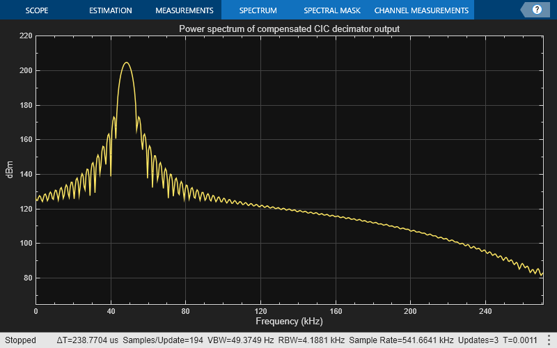
Create and configure two Spectrum Analyzer System objects to plot the power spectrum of the NCO output and of the compensated CIC decimator output.
specScope1 = spectrumAnalyzer(...
  'Method','welch', ...
  'Name','DSPDDC: NCO Output',...
  'SampleRate',Fs,...
  'FrequencySpan','start-and-stop-frequencies',...
  'StartFrequency',0,'StopFrequency',Fs/2,...
  'RBWSource', 'property', 'RBW', 4.2e3,...
  'Title', 'Power spectrum of NCO output',...
  'Position',[pos(1)+.8*pos(3) pos(2)+0.7*pos(4) pos(3:4)]);

FsCICcomp = Fs/(M1*M2);
specScope2 = spectrumAnalyzer(...
  'Method','welch', ...
  'Name','DSPDDC: Compensated CIC Decimator Output',...
  'SampleRate',FsCICcomp,...
  'FrequencySpan','start-and-stop-frequencies',...
  'StartFrequency',0, 'StopFrequency',FsCICcomp/2,...
  'RBWSource', 'property', 'RBW', 4.2e3,...
  'Title', 'Power spectrum of compensated CIC decimator output',...
  'Position',[pos(1)+.8*pos(3) pos(2)-0.7*pos(4) pos(3:4)]);
Processing Loop
In the processing loop, the mixer front-end digitally down converts the GSM signal to baseband. The CIC decimation and compensation filters downsample the signal by a factor of 128 and the programmable FIR filter decimates by another factor of 2 to achieve an overall decimation of 256. The resampling back-end performs additional application-specific filtering. Running the processing loop for 100 iterations is equivalent to processing around 1.1 ms of the resampled output.
for ii = 1:100
    gsmsig(:) = sine();         % GSM signal
    ncosig    = nco();          % NCO signal
    mixsig(:) = gsmsig.*ncosig; % Digital mixer

    % CIC filtering and compensation
    ycic = cfir(cicdec(mixsig));

    % Programmable FIR and sample-rate conversion
    yrcout = firrc(pfir(ycic));

    % Frequency and time-domain plots
    timeScope1(real(yrcout));
    timeScope2(imag(yrcout));
    specScope1(ncosig);
    specScope2(ycic);
end
release(timeScope1);
release(timeScope2);
release(specScope1);
release(specScope2);
Conclusion
In this example, you used DSP System Toolbox™ System objects to simulate the steady-state behavior of a fixed-point GSM digital down converter. The Time Scope and Spectrum Analyzer System objects enable you to analyze the various stages of a DDC.