WWV Digital Receiver - Synchronization and Detection
This example shows an implementation of a digital receiver that synchronizes to the time code information broadcast by radio station WWV and decodes it to display time information. The example uses the Simulink®, DSP System Toolbox™, and Stateflow® products with the MATLAB® Function block to achieve a simple noncoherent digital receiver.
What Is WWV?
WWV is the call sign of a US government radio station run by the National Institute of Standards and Technology in Fort Collins, Colorado. WWV transmits frequency reference standards and time code information. The transmitted time code is referenced to a Cesium clock with a timing accuracy of 10 microseconds and a frequency accuracy of 1 part in 100 billion. The time code is transmitted using a 100-Hz audio signal with pulse-width modulation using the IRIG-B time code format.
You can find more information on WWV at Radio Station WWV.
Introduction to Synchronization
Synchronization is a common problem in Communications applications. This example shows you one way of implementing a solution to this problem in Simulink. Consider the following simple model:

The Buffer Samples block maintains an internal circular buffer for efficient buffering of input samples. It uses a mode where a valid output frame is computed only when it receives a Boolean 'true' at the En_Out input port. The Frame Sync Logic subsystem outputs a Boolean 'true' when an appropriate frame, as expected by the Receiver, has been buffered. The same Boolean signal also acts as a trigger to the Receiver subsystem, which processes the valid frame. Due to this arrangement, the output sections of the Buffer Samples block and the Receiver subsystem only run when required. This arrangement is used in two places in this example, once for symbol synchronization and demodulation and then again for frame synchronization and decoding.
Exploring the Example
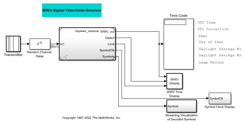
The example model consists of the following parts, which are described in the sections below:
Transmitter - Generates and transmits a BCD time code
Random Channel Delay - Adds random delay to the transmitted signal
Model - References dspwwv_receiver model through a Model (Simulink). This model consists of:
Receiver - Demodulates the received time code, synchronizes and locks in with the received signal, and detects the BCD symbols
Decoder - Decodes the BCD symbols
Display - displays the corresponding time and date information
Note that dspwwv does not support code generation, but dspwwv_receiver does.
Transmitter
This subsystem generates a Binary Coded Decimal (BCD) time code on an 100-Hz tone. The sampling rate (Ts) used by the Simulink model is 8000 samples/sec. The time code broadcast by WWV provides UTC (Coordinated Universal Time) information serially at a speed of 1 bit per second. It requires 60 bits, or one minute, to send the entire time code. Various bits in each time code convey the following information:
24 hour time (UTC)
UT1 time correction
Year
Day of year
Daylight Savings indicators
Leap seconds correction
Refer to the 'WWV Time Code Bits' and 'WWV Time Code Format' sections at the NIST website for more information on the time code. Depending on whether you select 'Current' or 'User-specified' for the Display time parameter on the transmitter subsystem mask, the subsystem generates the corresponding 60 BCD time code symbols. Each symbol is represented using Pulse Width Modulation (PWM) of an 100-Hz tone and is output from the Transmitter subsystem. One of the following possible symbols are transmitted each second:
MISS - No pulse is sent at the beginning of each frame, to indicate the start of a new frame
ZERO - A 170-ms pulse indicates a 0 bit
ONE - A 470-ms pulse indicates a 1 bit
MARKER - A 770-ms pulse is sent every 10 seconds for synchronization
The transmitted symbols are mapped to the following integer values in the Simulink model:
0 - MISS
1 - ZERO
2 - ONE
3 - MARKER
This transmitted tone is identical to the tone transmitted on the WWV subcarrier.
Random Channel Delay
This subsystem adds random delay to the transmitted signal. The receiver section synchronizes to the transmitted symbols and decodes the appropriate time code, even in the presence of an unknown delay.
Model - dspwwv_receiver Referenced Model
Double-click the Model block to open the dspwwv_receiver model. This model has all the components for appropriately demodulating, synchronizing, and detecting the transmitted signal. It consists of the following three subsystems:
R1 - Receiver
Double-click the Receiver Subsystem to view its component subsystems:
1) Downconvert and Downsample accepts as input the pulse width modulated signal. The subsystem demodulates the received signal by performing envelope detection, then performs lowpass filtering and downsamples by 80. Therefore, there are 100 samples for every transmitted symbol in the demodulated signal (dm). The output of this subsystem is a sequence of variable length square pulses.
2) AGC (Automatic Gain Control) estimates the amplitude of the dm signal, which is later used in thresholding the dm signal.
3) Symbol Timing Recovery and Buffer for Demod is used to achieve symbol synchronization and buffer the symbols for demodulation. It contains the following subsystems:
3.1) Leading Edge Detector takes in the demodulated signal dm and quantizes it into a Boolean signal. The Detect output signal is 'true' if the value of the dm signal is greater than the AGC value, otherwise it is 'false'. The subsystem also outputs the Boolean signal Edge that contains the rising edges of the dm signal.
3.2) Symbol Sync achieves symbol synchronization and creates a clock signal synchronized to the WWV signal. Note that the frame synchronization is done later on, in the Decoder section. Synchronization makes use of the Stateflow temporal logic feature. This Stateflow chart is composed of three parts:
SymbolSync - This chart is further divided into Sync State and Lock State charts
Clock Synchronization
Integration
Below are shown the Symbol Timing Recovery and Buffer for Demod subsystem and the Symbol Sync state chart.

3.2.1) SymbolSync performs symbol synchronization. The chart takes as input the rising edges (Edge) of the dm signal, which are approximately 100 samples apart.
The internal parameters of this chart are:
N1 - Actual number of samples between two edges
N1est - Estimate of the number of samples between two edges (initial value 100)
Nwin - Window in which to find another edge after N1est samples (default value 11 samples)
Nhalfwin - Half of the window length (default value 6)
Sync State - To start synchronization, this chart looks for a rising edge, followed by a period of silence (no edges) for approximately 100 samples, and then looks for another rising edge in a window centered at that point. If the chart succeeds in doing this, the system claims to be synchronized and assumes that the rest of the symbols are valid symbols. Otherwise, the chart waits for such a pattern to occur again and keeps waiting until it succeeds:
The 'Sync' state chart waits for an edge and then seeks silence (no other edge) for at least dly = ' N1est - Nhalfwin + 1 ' samples.
If this chart does not see silence in that duration (dly samples) and finds another edge, it treats the new edge as the reference edge and again seeks silence.
This chart repeats steps 1 and 2 until it succeeds in seeking silence for the next dly samples after the reference edge.
Once silence for dly samples is detected, this chart calculates how many samples (cnt) after dly samples it found another edge. If the next edge is found within the Nwin window, it transitions to the 'Lock' state to start receiving the subsequent symbols. If the next edge is not found within Nwin window samples, it discards the reference edge and starts searching for the reference edge again as described in steps 1-3.
Lock State - Once synchronized, this chart looks for the next symbol in a window centered at approximately every 100 samples and remains synchronized as long as it finds symbols. If the chart does not find any symbols for two consecutive times (approximately 200 samples), then it is no longer synchronized and tries to establish synchronization again as described above:
Once transitioned into the 'Lock' state, this chart assumes that the edges should now come in periodically (approximately every N1est samples).
The chart updates N1 to N1+Nhalfwin-cnt and ignores the next dly = N1-Nhalfwin+1 samples, and then searches for the next edge in a window of Nwin samples after that.
It keeps track of the number of samples in the window (cnt) after which it found the next edge. If it found an edge within the window, it again update N1 as mentioned above.
Based on the new cnt value, it calculates the new dly and starts looking for the new edge as mentioned above.
The chart allows for not having found an edge within Nwin window once to account for the MISS symbol, but if that happens two consecutive times it gets out of the Lock state and starts symbol synchronization again by transitioning into the Sync state.
3.2.2) Clock Synchronization generates a clock signal when a new rising edge of the dm signal is received. This way the clock is synchronized with the occurrence of a new edge, rather than with the Simulink clock running periodically at a fixed rate.
3.2.3) Integration generates a template step function with a 17-sample width to represent a ZERO symbol when an edge is found, this is, whenever a clock is generated. This signal is used by the AGC subsystem.
3.3) Symbol Buffer for Downstream Demod buffers samples corresponding to a symbol when it receives a clock signal (computed above in 3.2.2).
4) Symbol Demod and Frame Buffer is triggered every time it receives a nonzero clock signal. It uses the Vector Quantization block to perform symbol demodulation by comparing the input 'Symbols' buffer against the four possible symbol candidates (MISS, ZERO, ONE and MARKER). It outputs the symbol with the best match. The Delay Line block is used to buffer 60 consecutive symbols to create the 'WWV frame buffer.' The Frame Sync Logic subsystem preceding the Delay Line block looks for the occurrence of a consecutive MARKER and a MISS symbol, since this pattern indicates the start of a new WWV frame. The Delay Line block outputs a valid buffer only when this pattern in found. The subsequent IRIG-B decoder is also triggered at that instant.
R2 - IRIG-B Frame Decoder
The IRIG-B Frame Decoder triggered subsystem consists of a MATLAB Function block that is used to decode the IRIG-B format symbol frames into individual elements of the time code. This subsystem is triggered only when a valid WWV frame is received.
Display
The transmitted symbols are displayed on the Decoded Symbols scope and the decoded time code information is displayed on the 'Time code' display and 'WWV time code' window. The boxes on the 'WWV time code' window represent LEDs that light up when the corresponding signal is true. The LED corresponding to Daylight Savings is split into two parts, where the first part is the 'Daylight savings indicator 1' and the second part is the 'Daylight savings indicator 2.' The Clock Drift plot indicates the number of samples between rising edges of successive symbols ( symbolClk ) as they are received. This plot varies between 95 and 105 samples.
Using the dspwwv Example Model
Simulate the model. You will see the clock drift, the corresponding BCD time-code symbols and the current time displayed (shown below in that order.)


When the Display time parameter is set to 'Current', the model continues to display the current time, which is updated once every minute. You can change the Display time parameter of the Transmitted subsystem to 'User-defined' and specify any time you want to display.
You can also select a web site from the following list:
Americas
- América Latina (Español)
- Canada (English)
- United States (English)
Europe
- Belgium (English)
- Denmark (English)
- Deutschland (Deutsch)
- España (Español)
- Finland (English)
- France (Français)
- Ireland (English)
- Italia (Italiano)
- Luxembourg (English)
- Netherlands (English)
- Norway (English)
- Österreich (Deutsch)
- Portugal (English)
- Sweden (English)
- Switzerland
- United Kingdom (English)