Import AUTOSAR Adaptive Components to Simulink
R2026bCreate AUTOSAR Adaptive software component models in Simulink® by using one of these methods:
Import ARXML files with
arxml.importerand using thecreateComponentAsModelfunction.Create a Simulink model algorithm with blocks and signals and then configuring the model as an AUTOSAR Adaptive software component with the AUTOSAR Component Designer app. For more information, see Model AUTOSAR Adaptive Component and Elements in Simulink.
Create and configure an AUTOSAR Adaptive software component from an existing Simulink model. For an example, see Create AUTOSAR Adaptive Software Component Model.
This example shows how to create an AUTOSAR Adaptive software component model in Simulink from imported ARXML component descriptions.
Import AUTOSAR Adaptive Components from ARXML Files to Simulink
Use the MATLAB function createComponentAsModel to import AUTOSAR XML (ARXML) Adaptive software component descriptions and create Simulink models.
First, parse the ARXML description files and list the components they contain.
ar = arxml.importer({'fusion_app.arxml','radarService_app.arxml','radar_svc.arxml','stdtypes.arxml'});
names = getComponentNames(ar)
names = 2×1 cell
{'/RadarFusion/fusion' }
{'/RadarFusion/radarService'}
For each listed adaptive software component, use createComponentAsModel to create a Simulink representation. These commands create models named fusion and radarService.
createComponentAsModel(ar,"/RadarFusion/fusion",DataDictionary="radar.sldd");
Data dictionary 'radar.sldd' created.
createComponentAsModel(ar,"/RadarFusion/radarService",DataDictionary="radar.sldd");
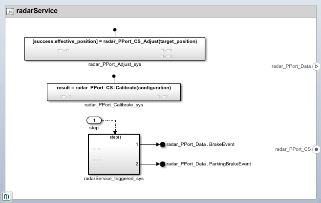
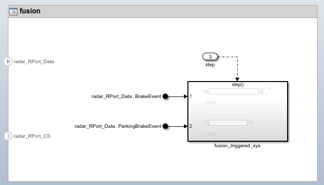
Each created model contains:
Simulink ports represent AUTOSAR Adaptive component provided and required service ports.
An AUTOSAR dictionary, which stores the imported AUTOSAR Adaptive element definitions
A software component service interface that honors the imported communication specifications
Inside the created subsystems and Simulink Function blocks, the ports are stubbed with Ground and Terminator blocks so that the model can be updated and simulated
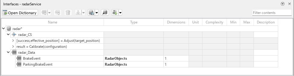
Each model is linked to data dictionary radar.sldd. Interfaces and data types were automatically imported to the Architectural Data section of the dictionary, and assigned to their associated ports. You can view the contents of the data dictionary by opening the Type Editor or Architectural Data Editor.
After you create an AUTOSAR Adaptive software component model, use the AUTOSAR Component Designer app to refine the configuration of the AUTOSAR Adaptive component. On the Apps tab, select AUTOSAR Component Designer. The AUTOSAR tab opens.
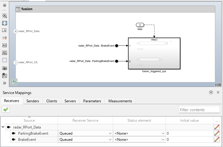
To view and edit service properties for AUTOSAR Adaptive component ports and elements open the Service Mappings Editor. Use this view to configure the software component service interface from an AUTOSAR Adaptive software component perspective in Simulink.
Develop AUTOSAR Adaptive Component Algorithms, Simulate, and Generate Code
After you create an AUTOSAR Adaptive software component model and refine the configuration, you develop the component. Create algorithmic model content that implements the component requirements.
The fusion component model that you created contains an initial stub implementation of the component behavior.
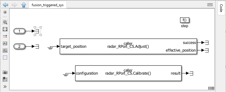
To implement the component requirements, replace the Terminator blocks with blocks that implement Simulink algorithms.
As you develop AUTOSAR Adaptive components, you can:
Simulate the component model individually or in a containing software architecture (requires System Composer™) or a test harness (requires Simulink Test™).
Generate ARXML component description files, service implementation code, and algorithmic C++ code for testing in Simulink or integration into AUTOSAR Runtime for Adaptive Applications (ARA). (AUTOSAR code generation requires Simulink Coder and Embedded Coder.)
For more information, see Component Development and Code Generation.

