Feed Model
An antenna feed usually uses a conventional transmission line through two electrically close terminals. The feed model and feed location are important variables in antenna analysis because the input impedance at the feed location affects the resulting radiation pattern directivity and gain of the antenna. An antenna can be fed using an open-wire transmission line or a coaxial feed through the ground plane. These feed systems directly impact the antenna impedance characteristics. Antennas in Antenna Toolbox™ use the delta-gap source feed model.
Delta-Gap Source Feed Model
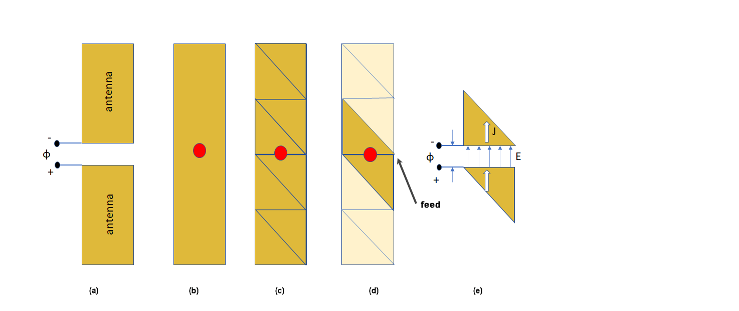
Consider an antenna with a voltage source ϕ connected between the terminals of the antenna as shown in (a). This approximate strip dipole antenna model is designed in Antenna Toolbox as shown in (b) along with the meshed structure in (c). The two highlighted triangles in (d) correspond to edge elements for the Rao-Wilton-Glisson (RWG) basis function. This feed model is the simplest model suited for RWG edge elements and it is called the delta-function generator or feeding edge model.
Delta-gap source models the feed assuming that the electric field exists only in the infinitesimally small gap between the terminals (Δ). In the case of RWG edge elements, the gap field is described using a delta-function generator or feeding edge model. This model assumes the peak value, Vi, of excitation voltage at the feed terminals and zero elsewhere. Basically, the excitation voltage is assumed to be a cosine function of time with a zero phase and an amplitude of Vi Volts. The incident electric field is defined as:
where:
φ — Electric potential
V — Voltage across the gap
Δ — Gap width
This electric field is also constant at the feed terminals and zero elsewhere.
Double-Edge Delta Source Feed Models
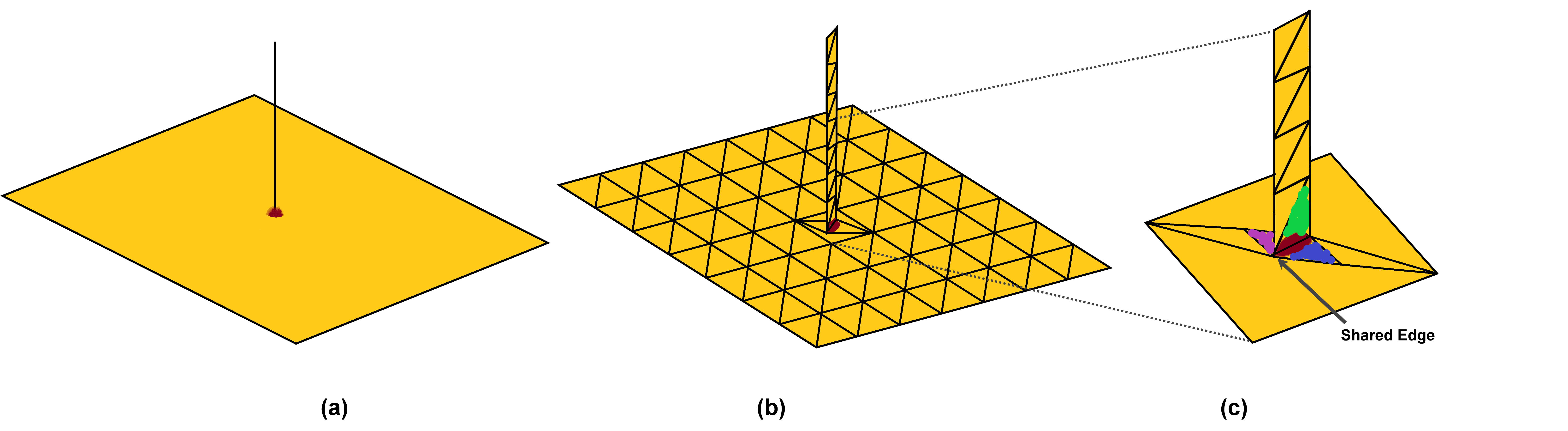
The monopole antenna design in Antenna Toolbox is shown in (a) along with the meshed structure in (b). The edge at the junction in (c) shows three triangles attached to it. The green and blue triangles in figure (c) form one RWG element, and the purple and green triangles form another RWG element. Thus, there are two RWG elements corresponding to single edge. This feed model is called the double-edge delta source feed model.
Monopole Antenna
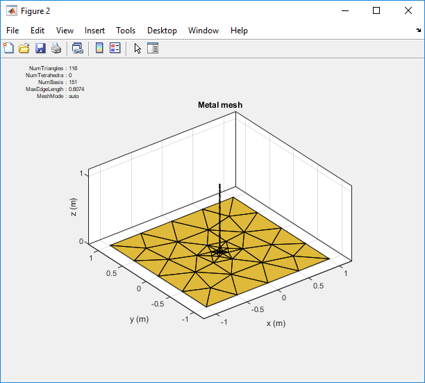
Create a monopole antenna using the monopole object and mesh the
antenna.
ant = monopole;
i = impedance(ant,75e6)
mesh(ant)
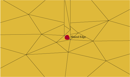
Zoom in on the feed region of the antenna. You will see that the feed point shares one common edge between the vertical radiator and the ground plane. In the case of the monopole antenna, this is where the gap exists. Here the voltage is 1 and the phase applied is 0 degrees. Everywhere else on the monopole the voltage is zero.
Multi-Edge Delta Source Feed Models
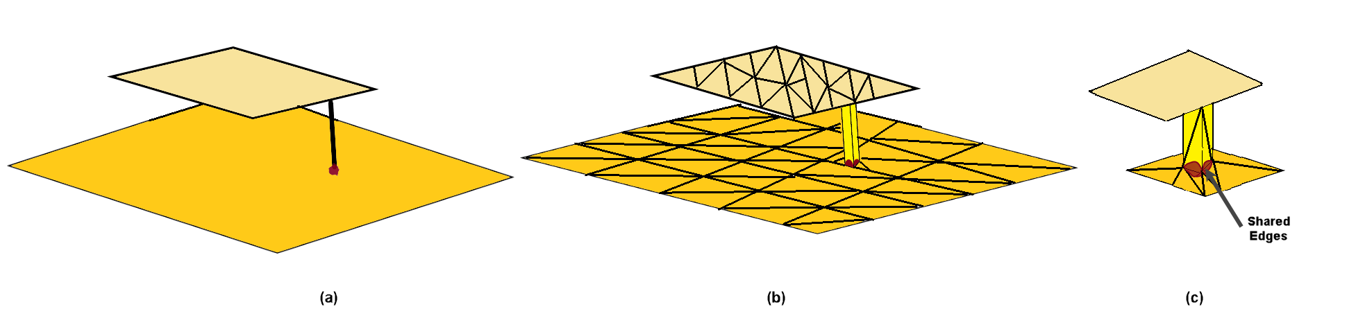
The microstrip patch antenna design in Antenna Toolbox is shown in (a) along with the meshed structure in (b). You can see that the strip connecting the two plates indicates two possible feeding edge positions. This is an example of multi-edge delta source feed model.
You can also improve on the single-edge feed by creating more accurate multi-edge
feeds using the pcbStack object.
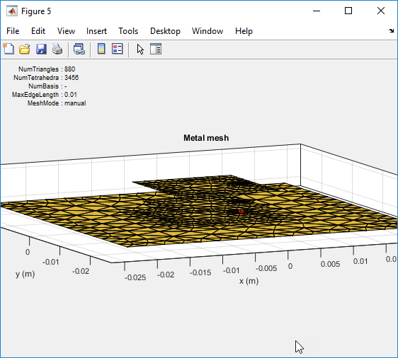
Consider this mesh for a stacked patch antenna with a solid-square feed model. Zoom in on the feed model. You can see that the solid-square feed has four edges connected to the ground plane. This feed-model increases the number of unknowns but represents the feed geometry more accurately.
Note
To create a stacked patch antenna, see Modeling and Analysis of Probe-Fed Stacked Patch Antenna.
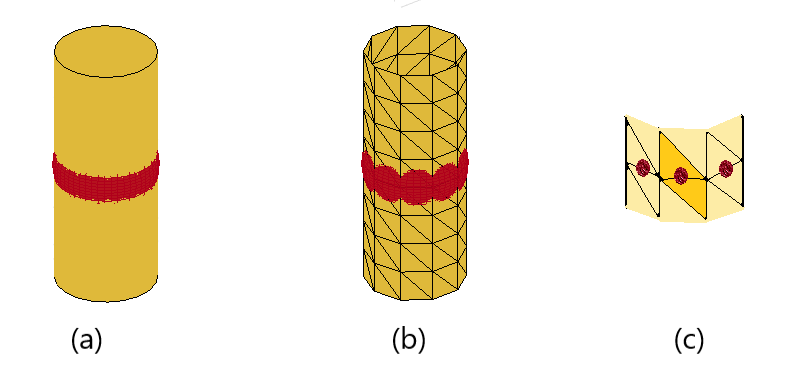
The cylindrical dipole antenna design in Antenna Toolbox is shown in (a) along with the meshed structure in (b). You can see the RWG edge elements in (c) around the cylindrical surface forming a closed structure. This is an example of multi-edge delta source feed model.