Analyze Electromagnetic Interference from Shielding Enclosures
This example shows how to model shielding enclosures and analyze electromagnetic interference from slots or apertures in the enclosure excited by the interior sources. Enclosure and the interior source is modeled using custom 3-D shapes and performance is evaluated at a particular distance away from the setup. The integrity of shielding enclosures for high-speed digital designs is compromised by slots and apertures for heat dissipation, CD-ROMs, input/output (I/O) cable penetration, and plate-covered unused connector ports among other possibilities. An understanding of energy coupling mechanisms to and from the enclosure as well as an experimentally demonstrated modeling approach is essential in minimizing the EMI and susceptibility risk in a new design.[1]
Define Enclosure and Slot Dimensions
Define the enclosure and slot dimensions in meters.
enclosureLength = 220e-3;
enclosureWidth = 300e-3;
enclosureHeight = 140e-3;
slotLength = 2e-3;
slotWidth = 120e-3;
Create Shielding Enclosure
Create a box with shape.Box shape using the defined enclosure dimensions.
box = shape.Box(Length=enclosureLength, Width=enclosureWidth, Height=enclosureHeight);
Create another box with slot dimensions. Subtract the slot shape from the enclosure box shape to get the final shielding enclosure shape.
slot = shape.Box(Length=enclosureLength/2, Width=slotWidth, Height=slotLength, Color="r");
box.Transparency = 0.3;
[~] = translate(slot,[enclosureLength/2 0 -50e-3]);
boxEnclosure = box - slot;
[~] = translate(boxEnclosure,[0 0 40e-3]);
show(boxEnclosure);
Create Source Feed-Probe
Create a circular feed-probe using shape.Circle and performing extrude operation on the box enclosure. It spans from top of the box where the feed is attached to the slot.
feed = shape.Circle(Radius=0.8e-3, Center=[0.05 0], NumPoints=20, Color="r");
[~] = translate(feed,[0 0 -0.11]);
[~] = rotateY(boxEnclosure,180);
antShape = extrude(boxEnclosure,feed,Height=0.12);
[~] = rotateY(antShape,180);
show(antShape)
Create a custom antenna with the enclosure shape and visualize it.
ant = customAntenna(Shape=antShape);
[~] = createFeed(ant,[-0.05 0 0.11],20);
show(ant);

Analyze Enclosure Setup
Calculate E-H fields at a distance of 3m along the x-axis from the enclosure setup.
[E,H] = EHfields(ant,linspace(0.7e9,1.6e9,100),[3 0 0]');
Calculate the E-field magnitude.
Et = abs(E);
Et = sqrt(Et(1,:).^2+Et(2,:).^2+Et(3,:).^2);
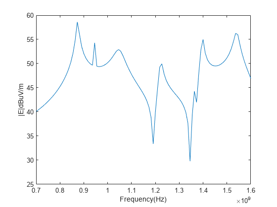
Plot the E-field magnitude against 700 MHz to 1.6 GHz frequency range.
plot(linspace(0.7e9,1.6e9,100),10*log10(Et./1e-6));
xlabel("Frequency(Hz)");
ylabel("|E|dBuV/m");
Conclusion
As seen from the E-field magnitude plot across the 700 MHz to 1.6 GHz frequency range, electromagnetic interference is significant when the larger dimension of the slot is comparable to half-wavelength at the respective frequency.
References
[1] Min Li, J. Nuebel, J.L. Drewniak, R.E. DuBroff, T.H. Hubing, and T.P. Van Doren. “EMI from Cavity Modes of Shielding Enclosures-FDTD Modeling and Measurements.” IEEE Transactions on Electromagnetic Compatibility 42, no. 1 (February 2000): 29–38. https://doi.org/10.1109/15.831702.