Analysis of Broad-Wall Slotted Array Waveguide for High Frequency Applications
This example shows how to create custom slots in a waveguide antenna and analyze its performance.
Create Slotted Waveguide
Create a slotted waveguide using default geometry parameters.
a = waveguideSlotted(Tilt=180, TiltAxis=[1 0 1]);
Create custom slots in the waveguide.
Transverse Slotted Array
Transverse slots result in a very high value of their normalized resistance and they cannot be matched to the characteristic waveguide impedance. So, they have no practical importance.
a.SlotAngle = 90;
a.SlotOffset = 0;
show(a);
title("Transverse Slotted Array Waveguide Antenna");
X-shape Slotted Array
The cross(X) slots can generate a circular polarized wave with a good axial ratio performance. The slots are oriented to form an orthogonal pair of slots which eventually generate a circular polarized wave. The theory of cross slots also suggests that the slots should be ideally equal to half of the free space wavelength.
rSlot1 = antenna.Rectangle(Length=0.053, Width=0.0065);
rSlot1 = rotateZ(rSlot1,45);
rSlot2 = antenna.Rectangle(Length=0.053, Width=0.0065);
rSlot2 = rotateZ(rSlot2,-45);
xSlot = rSlot1 + rSlot2;
a.Slot = xSlot;
a.SlotAngle = 90;
a.SlotOffset = 0;
show(a);
title("X-shape Slotted Array Waveguide Antenna");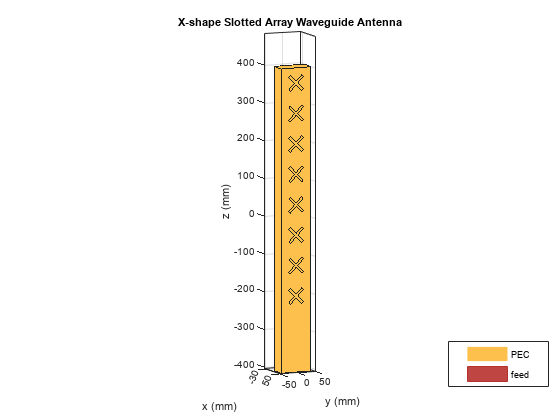
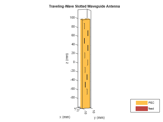
Longitudinal Linear Traveling-Wave Slotted Waveguide
The array consists of radiating slots of different electrical lengths. Due to inherent property, each of them will resonate at their own individual resonance frequency. If the slot length and positions are chosen in such a way that the lower cut-off frequency and higher cut-off frequency of the nth slot overlaps with the higher and lower cut-off frequencies of the (n-1)th and (n+1)th slots respectively, then the complete array is expected to give a wide band response resulting in log-periodic dipole array. Slot Offset on broad wall slots are parallel to the waveguide centerline and they are blocking the transversal current components on the waveguide's broad wall. The polarization of these slots is vertical when the waveguide is held parallel to the ground and the transversal current component is zero on the centerline of the broad wall, however, if one slot moves closer to the narrow walls, the transversal current component increases. Therefore, the radiation amplitude of these slots increases as they move away from the centerline and that is why they are called offset slots. This is the most widely used slot type and this design is taken from [1].
% Create Slots
r1 = antenna.Rectangle(Length=12.7e-3, Width=1e-3);
r2 = antenna.Rectangle(Length=12.6e-3, Width=1e-3);
r3 = antenna.Rectangle(Length=12.5e-3, Width=1e-3);
r4 = antenna.Rectangle(Length=12.6e-3, Width=1e-3);
r5 = antenna.Rectangle(Length=12.4e-3, Width=1e-3);
r6 = antenna.Rectangle(Length=12.3e-3, Width=1e-3);
r7 = antenna.Rectangle(Length=12.2e-3, Width=1e-3);
r8 = antenna.Rectangle(Length=12e-3, Width=1e-3);
r9 = antenna.Rectangle(Length=12e-3, Width=1e-3);
r10 = antenna.Rectangle(Length=12.2e-3, Width=1e-3);

% Create Waveguide
ant1 = waveguideSlotted(Length=199.37e-3, Width=19e-3, NumSlots=10,...
     Height=9.5e-3, Slot=[r1 r2 r3 r4 r5 r6 r7 r8 r9 r10], SlotToTop=14.476e-3,...
     SlotSpacing=16.45e-3, SlotOffset=...
     [4.5e-3 4.3e-3 4.1e-3 4.5e-3 3.7e-3 3.3e-3 2.9e-3 2.3e-3 1.9e-3 1.9e-3],...
     FeedHeight=6.6e-3, ClosedWaveguide=0, FeedOffset=[-91.5e-3 0],...
     FeedWidth=0.04e-3, Tilt=180, TiltAxis=[1 0 1]);
figure
show(ant1);
title("Traveling-Wave Slotted Waveguide Antenna");
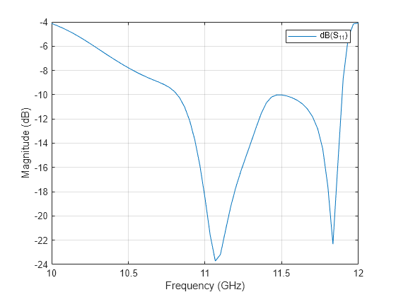
Plot Reflection Coefficient
Plot the reflection coefficient for this antenna over the frequency band of 10 GHz to 12 GHz and a reference impedance of 50 ohms.
s = sparameters(ant1,linspace(10e9,12e9,61));
figure
rfplot(s);
Radiation pattern
The most significant effect to be considered in the design process are internal and external mutual coupling between slots. The internal mutual couplings are caused by the partial reflections of the incident electromagnetic wave from succeeding slots in a waveguide. These partial reflections cause a considerable displacement of the EM field inside the waveguide.
figure
pattern(ant1,12e9,0,-100:100,CoordinateSystem="Rectangular");
Conclusion
The models of the Slotted waveguide antenna have been built and analyzed and agree well with results reported from [1].
References
[1] Montesinos Ortego, "Contribution to the design of waveguide fed compound slot arrays by means of equivalent circuit modeling".
[2] Zunnurain Ahmad,"Design and Implementation of Quasi Planar K-Band Array Antenna Based on Travelling Wave Structures".