About Aerospace Coordinate Systems
Fundamental Coordinate System Concepts
Coordinate systems allow you to keep track of an aircraft or spacecraft position and orientation in space. The Aerospace Blockset™ coordinate systems are based on these underlying concepts from geodesy, astronomy, and physics.
Definitions
The blockset uses right-handed (RH) Cartesian coordinate systems. The right-hand rule establishes the x-y-z sequence of coordinate axes.
An inertial frame is a nonaccelerating motion reference frame. In an inertial frame, Newton's second law holds: force = mass x acceleration. Loosely speaking, acceleration is defined with respect to the distant cosmos, and an inertial frame is often said to be nonaccelerated with respect to the fixed stars. Because the Earth and stars move so slowly with respect to one another, this assumption is a very accurate approximation.
The angular positions of background stars change so gradually that they can be considered fixed, so you can treat the frame as inertial. However, in reality, these stars move at speeds exceeding 100 km/s relative to each other and the Earth.
Strictly defined, an inertial frame is a member of the set of all frames not accelerating relative to one another. A noninertial frame is any frame accelerating relative to an inertial frame. Its acceleration, in general, includes both translational and rotational components, resulting in pseudoforces (pseudogravity, as well as Coriolis and centrifugal forces).
The blockset models the Earth shape (the geoid) as an oblate spheroid, a special type of ellipsoid with two longer axes equal (defining the equatorial plane) and a third, slightly shorter (geopolar) axis of symmetry. The equator is the intersection of the equatorial plane and the Earth surface. The geographic poles are the intersection of the Earth surface and the geopolar axis. In general, the Earth geopolar and rotation axes are not identical.
Latitudes parallel the equator. Longitudes parallel the geopolar axis. The zero longitude or prime meridian passes through Greenwich, England.
Approximations
The blockset makes two standard approximations in defining coordinate systems relative to the Earth.
The Earth surface or geoid is an oblate spheroid, defined by its longer equatorial and shorter geopolar axes. In reality, the Earth is slightly deformed with respect to the standard geoid.
The only noninertial effect in Earth-fixed coordinates is due to the Earth rotation about its axis. This system is a rotating, geocentric system. The Aerospace Blockset does not take into account the acceleration of the Sun within the galaxy or the acceleration of the galaxy itself through the cosmos.
Passive Transformations
All quaternions in Aerospace Blockset are passive transformations. In a passive transformation, the vector is unchanged and the coordinate system in which it is defined is rotated. For more information on transformations, see Active and passive transformations.
Motion with Respect to Other Planets
The blockset uses the standard WGS-84 geoid to model the Earth. You can change the equatorial axis length, the flattening, and the rotation rate.
You can represent the motion of spacecraft with respect to any celestial body that is well approximated by an oblate spheroid by changing the spheroid size, flattening, and rotation rate. If the celestial body is rotating westward (retrogradely), make the rotation rate negative.
Coordinate Systems for Modeling
Modeling aircraft and spacecraft is simplest if you use a coordinate system fixed in the body itself. In the case of aircraft, the forward direction is modified by the presence of wind, and the craft motion through the air is not the same as its motion relative to the ground.
See Equations of Motion for further details on how the blockset implements body and wind coordinates.
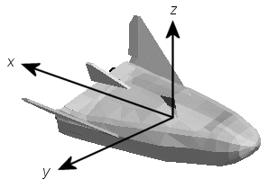
Body Coordinates
The noninertial body coordinate system is fixed in both origin and orientation to the moving craft. The craft is assumed to be rigid.
The orientation of the body coordinate axes is fixed in the shape of body.
The x-axis points through the nose of the craft.
The y-axis points to the right of the x-axis (facing in the pilot's direction of view), perpendicular to the x-axis.
The z-axis points down through the bottom the craft, perpendicular to the xy plane and satisfying the RH rule.
Translational Degrees of Freedom
Translations are defined by moving along these axes by distances x, y, and z from the origin.
Rotational Degrees of Freedom
Rotations are defined by the Euler angles P, Q, R or Φ, Θ, Ψ.
| P or Φ | Roll about the x-axis |
| Q or Θ | Pitch about the y-axis |
| R or Ψ | Yaw about the z-axis |

Unless otherwise specified, by default the software uses ZYX rotation order for Euler angles.
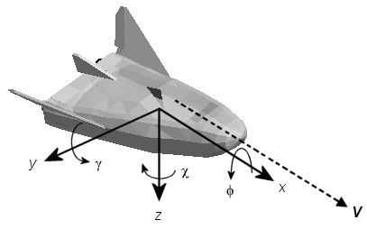
Wind Coordinates
The noninertial wind coordinate system has its origin fixed in the rigid aircraft. The coordinate system orientation is defined relative to the craft velocity V.
The orientation of the wind coordinate axes is fixed by the velocity V.
The x-axis points in the direction of V.
The y-axis points to the right of the x-axis (facing in the direction of V), perpendicular to the x-axis.
The z-axis points perpendicular to the xy plane in whatever way needed to satisfy the RH rule with respect to the x- and y-axes.
Translational Degrees of Freedom
Translations are defined by moving along these axes by distances x, y, and z from the origin.
Rotational Degrees of Freedom
Rotations are defined by the Euler angles Φ, γ, χ:
| Φ | Bank angle about the x-axis |
| γ | Flight path about the y-axis |
| χ | Heading angle about the z-axis |
Unless otherwise specified, by default the software uses ZYX rotation order for Euler angles.
Coordinate Systems for Navigation
Modeling aerospace trajectories requires positioning and orienting the aircraft or spacecraft with respect to the rotating Earth. Navigation coordinates are defined with respect to the center and surface of the Earth.
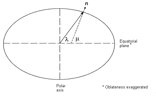
Geocentric and Geodetic Latitudes
The geocentric latitude λ on the Earth surface is defined by the angle subtended by the radius vector from the Earth center to the surface point with the equatorial plane. This definition assumes Earth as a perfect sphere, considering all points on the surface to be equidistant from the center of the Earth. However, because Earth is actually an oblate spheroid, the geocentric latitude does not accurately reflect the surface curvature in terms of the actual distance from the equator or the poles.
The geodetic latitude μ on the Earth surface is defined by the angle between the equatorial plane and the normal to the reference ellipsoid that best approximates Earth's surface at that point. The reference ellipsoid has a smaller radius at the poles and a larger radius at the equator, matching Earth's shape more closely than a sphere would. Geodetic latitude is commonly used in mapping and navigation because it provides a more accurate representation of the location of a point on Earth's surface.
NED Coordinates
The north-east-down (NED) system is a noninertial system with its origin fixed at the center of gravity of the ground station, aircraft, or spacecraft. The NED axes are oriented along the geodetic directions defined by the Earth surface. The NED system is a type of local tangent plane coordinate system, which means it is defined relative to a specific location on Earth, defined by latitude, longitude and altitude, typically where the measurement is being made or the vehicle, such as an aircraft or drone, is operating.
The x-axis points north parallel to the geoid surface, in the polar direction.
The y-axis points east parallel to the geoid surface, along a latitude curve.
The z-axis points downward, toward the Earth surface, antiparallel to the outward normal n of the surface.
Flying at a constant altitude means flying at a constant
zabove the Earth's surface.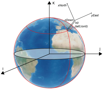
ECI and ECEF Coordinates
ECI Coordinates. The Earth-centered inertial (ECI) system is considered non-rotating and is generally treated as inertial for most applications, despite the equinox and equatorial plane experiencing very slight movements over time. For high-precision orbit calculations, the ECI system is recognized as truly inertial, especially when the equator and equinox are defined for a specific epoch, such as J2000. Aerospace functions and blocks that use a specific realization of the ECI coordinate system include this information in their documentation. The origin of the ECI system is established at the Earth's center, making this system particularly useful for describing the orbits of satellites and other celestial bodies in space. The reference plane for the ECI system is the mean equatorial plane.
The x-axis is aligned with the celestial sphere, pointing towards the vernal equinox (the first point of Aries ♈), which is the imaginary point in space found at the intersection of the Earth's equatorial plane and the plane of the Earth's orbit around the sun (the ecliptic plane).
The y-axis extends 90 degrees east from the x-axis within the equatorial plane.
The z-axis extends upwards from the North Pole, completing the right-handed coordinate system.
The International Celestial Reference Frame (ICRF) can be treated as equal to the ECI coordinate system realized at J2000 (Jan 1 2000 12:00:00 TT).
To describe a point in space, you need a frame of reference that does not rotate with respect to the stars. The ICRF, with the origin at the center of the Earth and orthogonal vectors I, J, and K, is used as the frame of reference. The fundamental plane is the IJ-plane, which is closely aligned with the equator with a small offset that changes over time because of precession and nutation of the rotation axis of the Earth.
The origin of the ICRF is located at the barycenter of the solar system. The ICRF axes are oriented in a space-fixed manner, meaning they do not kinematically rotate relative to distant objects in the universe.
ECI Applications
The ECI system does not rotate with the Earth, making it simpler to model the motion of satellites and other celestial bodies in space.
The ECI system is useful for analyzing and predicting the orbits of objects in an inertial space framework.
The inertial and Earth-fixed z-axes are not perfectly aligned due to the effects of polar motion, precession, and nutation.
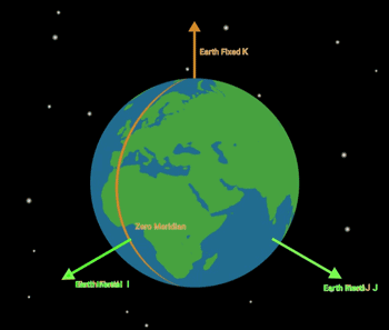
ECEF Coordinates. The Earth-centered, Earth-fixed (ECEF) system is a non-inertial frame that rotates alongside the Earth, with its origin stationed at the Earth's center. The reference plane for this system is the mean equatorial plane. In the ECEF system:
The x-axis extends outward from the point where the Earth's equatorial plane intersects the prime meridian (0° longitude).
The z-axis projects upward from the North Pole.
The y-axis extends eastward, perpendicular to the x-z plane, adhering to the right-hand (RH) rule for coordinate systems.
ECEF Applications
The ECEF system adheres to the right-hand (RH) rule for coordinate systems, making it ideal for mapping, navigation, and positioning tasks on the planet.
ECEF coordinates change with time for a given point on the Earth's surface due to Earth's rotation, which is useful for real-time applications like GPS.
Precession, Nutation and Rotation
Precession
Precession refers to the slow movement of the axis of the planet's rotation. More specifically, precession is the gradual shift in the direction of Earth's axis of rotation, which causes the position of the celestial poles to change over time. This movement is similar to the wobble seen in a spinning top as its speed decreases. The precession of the Earth's axis takes about 26,000 years to complete a full cycle. This phenomenon affects the timing of the seasons and the visibility of stars from Earth over long periods.
Nutation
Nutation is a smaller, more complex motion superimposed on the precession of the Earth's rotation axis. Nutation is a slight "nodding" or oscillation in the Earth's axis of rotation. Nutation causes the Earth's tilt to vary slightly over a period of 18.6 years. This variation is due to the gravitational influences of the Moon and, to a lesser extent, the Sun on the Earth's equatorial bulge. Nutation affects the precise position of the celestial poles and equinoxes, but its effects are much smaller compared to precession.
Rotation
Rotation refers to the spinning of the Earth around its own axis. This rotation defines day and night. The Earth rotates from west to east, which is why the Sun appears to rise in the east and set in the west. The Earth completes one full rotation approximately every 24 hours. The speed of the Earth's rotation is not perfectly constant. The rotational speed varies slightly due to complex interactions with the Moon and the Sun, as well as geophysical processes within the Earth itself. However, these variations are so small that, for most practical purposes, you can consider the Earth's rotation period as constant.
Comparison Between ECI and ECEF Coordinates. The ECI and ECEF coordinate systems are two fundamental frameworks used to represent the positions and velocities of objects in space and on the Earth's surface. Each system is uniquely characterized and applied in various fields such as satellite navigation, aerospace engineering, and geodesy. The ECI system is inertial, meaning it does not rotate with the Earth, whereas the ECEF system rotates in alignment with the Earth's surface.
Both the ECI and ECEF systems have their origins at the Earth's center of mass. A key difference between them is their angular orientation in the xy plane. This difference is quantified by the Earth rotation angle (ERA) or Greenwich sidereal angle, which measures the angle between the x-axis of the ECI and ECEF systems.
Satellite positions are often defined relative to the ECI frame, which aligns with the ICRF for satellite applications. The ICRF is essential because the Earth's rotation axis changes over time due to precession, nutation, and rotation. Therefore, an inertial frame with fixed axes in inertial space, typically defined at the epoch of J2000 (January 1, 2000, 12:00), is used. The z-axis of the ICRF frame aligns with the Earth's rotation axis as of the J2000 epoch. In contrast, the z-axis of the ECEF frame represents the rotation axis of Earth at the current time.
The transformation from ECI to ECEF is achieved through the IAU2000/2006
reduction, which accounts for axial precession and nutation, providing an adequate
adjustment for most applications. For enhanced fidelity, time-varying terms such as
Earth orientation parameters (EOPs) may be included. Using functions like dcmeci2ecef and eci2ecef can significantly improve the accuracy of these
transformations.
Coordinate Systems for Display
Several display tools are available for use with the Aerospace Blockset product. Each tool has a specific coordinate system for rendering motion.
MATLAB Graphics Coordinates
See the Axes Appearance for more information about the MATLAB® Graphics coordinate axes.
MATLAB Graphics uses this default coordinate axis orientation:
The x-axis points out of the screen.
The y-axis points to the right.
The z-axis points up.
FlightGear Coordinates
FlightGear is an open-source, third-party flight simulator with an interface supported by the blockset.
Work with the Flight Simulator Interface discusses the blockset interface to FlightGear.
See the FlightGear documentation at
www.flightgear.orgfor complete information about this flight simulator.
The FlightGear coordinates form a special body-fixed system, rotated from the standard body coordinate system about the y-axis by -180 degrees:
The x-axis is positive toward the back of the vehicle.
The y-axis is positive toward the right of the vehicle.
The z-axis is positive upward, that is, wheels typically have the lowest z values.
AC3D Coordinates
AC3D is a low-cost, widely used, geometry editor available from https://www.inivis.com. Its body-fixed coordinates are formed by
inverting the three standard body coordinate axes:
The x-axis is positive toward the back of the vehicle.
The y-axis is positive upward, that is, wheels typically have the lowest y values.
The z-axis is positive to the left of the vehicle.

References
[1] Recommended Practice for Atmospheric and Space Flight Vehicle Coordinate Systems, R-004-1992, ANSI/AIAA, February 1992.
[2] Rogers, Robert M., Applied Mathematics in Integrated Navigation Systems. Reston, VA: AIAA, 2000.
[3] Sobel, Dava, Longitude, Walker & Company, 1995.
[4] Stevens, Brian L., and Frank L. Lewis. Aircraft Control and Simulation. 2nd ed., New York: Wiley-Interscience, 2003.
[5] Thomson, William Tyrrell. Introduction to Space Dynamics. Rev. ed. New York: John Wiley & Sons, 1986.
External Websites
You can also select a web site from the following list:
Americas
- América Latina (Español)
- Canada (English)
- United States (English)
Europe
- Belgium (English)
- Denmark (English)
- Deutschland (Deutsch)
- España (Español)
- Finland (English)
- France (Français)
- Ireland (English)
- Italia (Italiano)
- Luxembourg (English)
- Netherlands (English)
- Norway (English)
- Österreich (Deutsch)
- Portugal (English)
- Sweden (English)
- Switzerland
- United Kingdom (English)